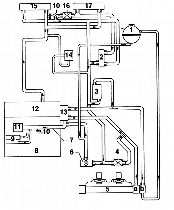
24v Vr6 Cooling System Diagram

Vr6 Coolant System Diagram Re: vr6 coolant system diagram. here's one observation on this diagram is that it shows general flows, but the flow of coolant is dependent on the thermostats position (open vs closed). for example, with the atf cooler heater (#3 on diagram) when the thermostat is closed, this actually acts to heat up the transmission fluid. To install, reverse removal procedure. use new self locking nuts and coolant. ensure engine mounts are installed to original location. align all engine supports with mount bushings before tightening mount bolts. tighten bolts to specification. see torque specifications . 1994 volkswagen corrado slc 2.8l vr6.

Diagram Volkswagen Vr6 Coolant System Diagram Mydiagram Online Fig. 4: identifying 2.8l vr6 cylinder head (gti & jetta aaa engine) courtesy of volkswagen united states, inc. 2) remove camshaft position sensor, "o" ring and spacer ring. remove bracket for 42 pin connector and water pump. remove ignition coil, chain tensioner and seal. Vr6 coolant pipe and thermostat housing diy. this is a diy on replacing the vw vr6 coolant pipe, aka crack pipe, and thermostat housing. on the aaa vr6 engine. we learn how to replace the pipe and a few things to be careful of. this is another video in the mk3 diy series. you can check out the mk3 gti walk around video i did. General overview of 24v vr6 mk4 jetta coolant tube "crack pipe" and thermostat housing locations and replacement tips.dont forget to like and subscribe!!. Lock support and front bumper. drain cooling system. disconnect cooling fan and thermoswitch. fig. 2: releasing accessory drive belt tensioner courtesy of volkswagen united states, inc. 3) label and disconnect all electrical wiring, control cables, coolant hoses and vacuum hoses from engine transaxle assembly.

Diagram Volkswagen Vr6 Coolant System Diagram Mydiagram Online General overview of 24v vr6 mk4 jetta coolant tube "crack pipe" and thermostat housing locations and replacement tips.dont forget to like and subscribe!!. Lock support and front bumper. drain cooling system. disconnect cooling fan and thermoswitch. fig. 2: releasing accessory drive belt tensioner courtesy of volkswagen united states, inc. 3) label and disconnect all electrical wiring, control cables, coolant hoses and vacuum hoses from engine transaxle assembly. 60 posts · joined 2008. #1 · oct 20, 2011. i'm still fighting an apparent overheating issue with my '01 gti vr6. i'm wondering if anyone knows of where i can find a diagram for the coolant flow. i've had a problem with the plastic connectors aging and breaking, i've replaced them, but at least one hose i know has a check valve built into it. Cooling system components, removing and installing (page 19 7) cooling system components, engine side 1 pressure cap check with v.a.g 1274 test instrument and v.a.g 1274 9 adapter test pressure 1.4 1.6 bar 2 o ring replace if damaged 3 coolant recovery bottle check for leaks in cooling system using v.a.g 1274 test instrument and v.a.g1274.

Diagram Jetta Vr6 Coolant Diagram Wiring Schematic Mydiagram Online 60 posts · joined 2008. #1 · oct 20, 2011. i'm still fighting an apparent overheating issue with my '01 gti vr6. i'm wondering if anyone knows of where i can find a diagram for the coolant flow. i've had a problem with the plastic connectors aging and breaking, i've replaced them, but at least one hose i know has a check valve built into it. Cooling system components, removing and installing (page 19 7) cooling system components, engine side 1 pressure cap check with v.a.g 1274 test instrument and v.a.g 1274 9 adapter test pressure 1.4 1.6 bar 2 o ring replace if damaged 3 coolant recovery bottle check for leaks in cooling system using v.a.g 1274 test instrument and v.a.g1274.

Comments are closed.