3 Wire Coolant Temperature Sensor Wiring Diagram Asmaaakas

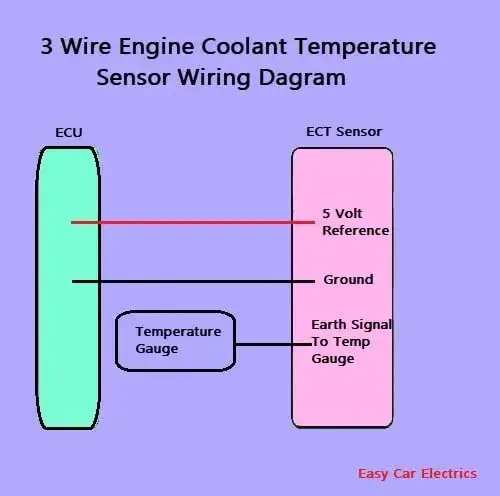
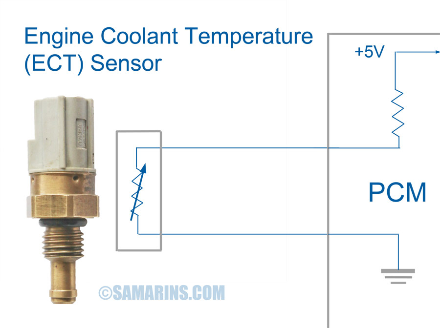
1 2 3 Wire Coolant Temperature Sensor Wiring Diagram The specific 3 wire coolant temperature sensor wiring diagram will vary slightly depending on the vehicle make and model. however, the fundamental principles remain consistent. a typical diagram will show the three wires connected to the sensor,. 3 wire coolant temperature sensor wiring diagram. the two wires, a “5 volt reference”, and a “ground wire” go to the ecu, and the third wire “earth 1 wire for temp gauge” goes to the cluster mounted temperature gauge by providing an earth link to the temperature gauge. in three wire coolant temp sensors, the ecu does not control the.

3 Wire Coolant Temperature Sensor Wiring Diagram Asmaaakasha The wiring diagram for a 3 wire coolant level sensor typically includes three distinct wires: power, ground, and signal wire. the power wire supplies the sensor with electrical power, allowing it to function properly. the ground wire acts as a return path for the electrical current, completing the circuit. the signal wire is responsible for. The actual fan switching is done via a signal from the ecu to the fan relay. the haynes manual says : testing the temp sensor measure the resistance with the ve probe on the terminal and the ve probe on the body of the sensor. 2001 and later models. resistance at 80c = 2.1 to 2.6 k ohms. Hummertech: thanks, that diagram was exactly what i was looking for! bill ford: 3 wire ect sensor pn 12551708 and connector pn 12102748. 1993 gmc yukon 2dr 4x4, 6.0l 4l80e swap, wheatley tune, 3 inch magnaflow true duals, 6.5 inch dick cepek stage 1 lift, 35's, 4.56 gears, front posi lok. reply with quote. The wiring diagram consists of several components which are connected to your car’s electrical system by wires. the sensor’s output signal is sent to a gauge or a warning light, where it is measured and monitored. the gauge or warning light is then activated if there is a problem with the cooling system. it is also useful to know the type.

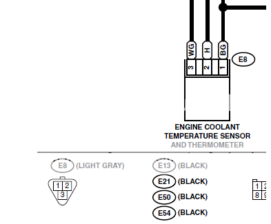
3 Wire Coolant Temperature Sensor Wiring Diagram Knittystash Hummertech: thanks, that diagram was exactly what i was looking for! bill ford: 3 wire ect sensor pn 12551708 and connector pn 12102748. 1993 gmc yukon 2dr 4x4, 6.0l 4l80e swap, wheatley tune, 3 inch magnaflow true duals, 6.5 inch dick cepek stage 1 lift, 35's, 4.56 gears, front posi lok. reply with quote. The wiring diagram consists of several components which are connected to your car’s electrical system by wires. the sensor’s output signal is sent to a gauge or a warning light, where it is measured and monitored. the gauge or warning light is then activated if there is a problem with the cooling system. it is also useful to know the type. By shawnr » wed jul 14, 2021 3:22 pm. has anyone here successfully used a gm 3 wire coolant temp sensor on their build. my intake only has 1 port for a temp sensor and since i am using it to run the ms3, my temp gauge on my dash no longer functions. the manual mentions using 1 wire for ecu and the other one for the gauge. Here's the ect sensor diagram that subaru has in the 2000 2004 mechanism & function section of the fsm. i've added notations that clarify what it's showing, based on the disassembly. note that it indicated only one temperature sensing device (2), but the drawing, in fact, includes both. to contrast, here's the corresponding diagram from the.

Comments are closed.