7 4 Mercruiser Engine Cooling Water Line Diagram

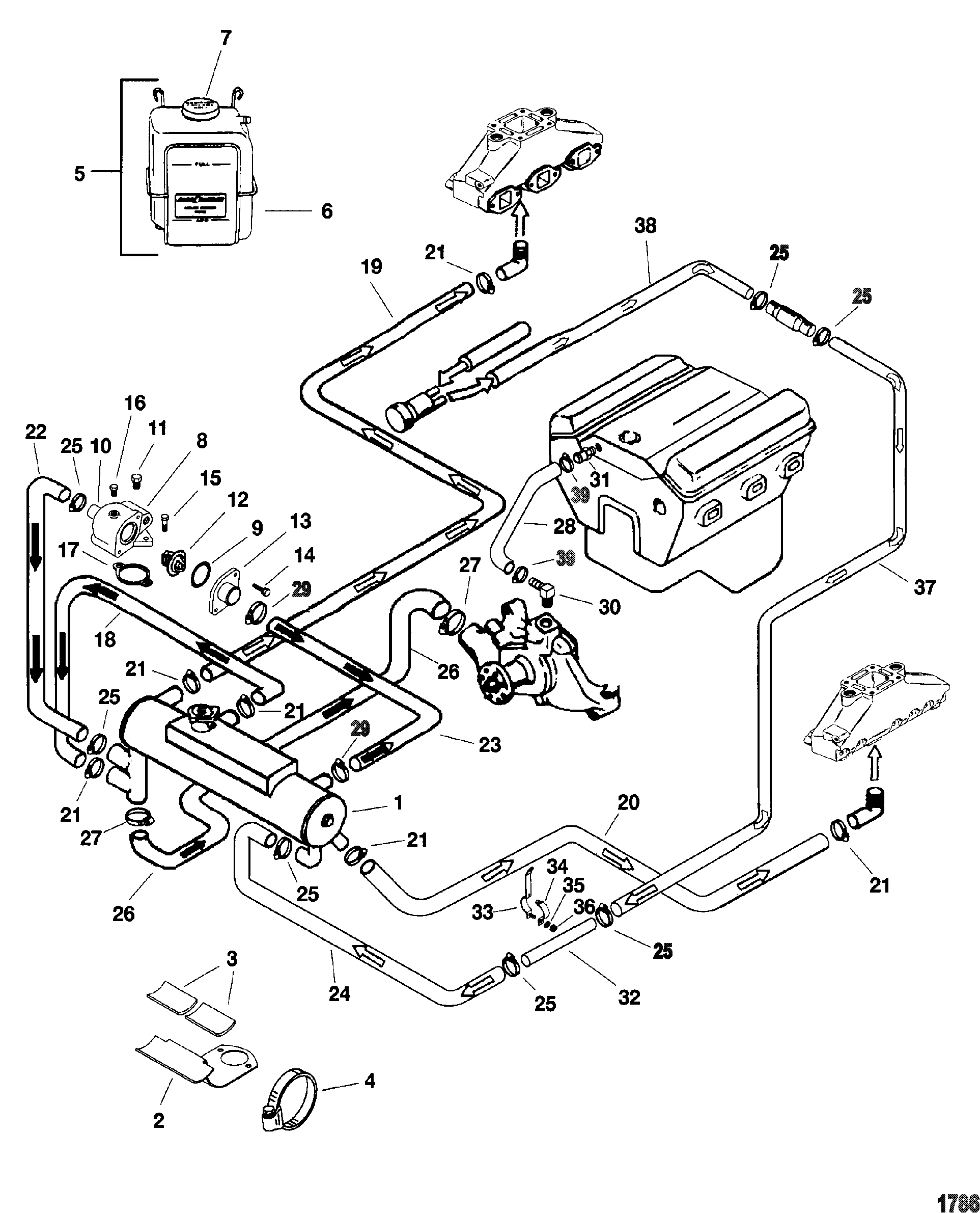
Diagram 7 4 Mercruiser Engine Cooling Diagram Mydiagram Online View online or download mercury mercruiser mie 7.4l mpi service manual. water in engine. 105. closed cooling system water flow diagram. 876. Rare: mercruiser v8 fresh water cooled, fresh water through manifolds water flow diagram: last edited by rossjo on tue nov 09, 2010 7:55 pm, edited 2 times in total. captain ross, 2009 trojan boater of the year.

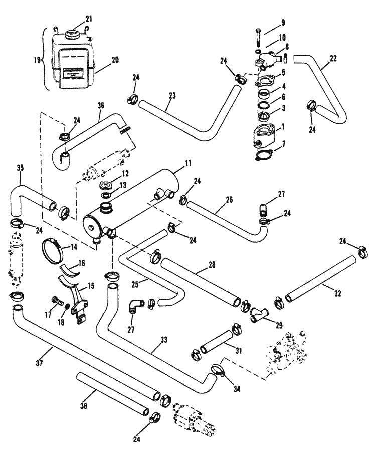
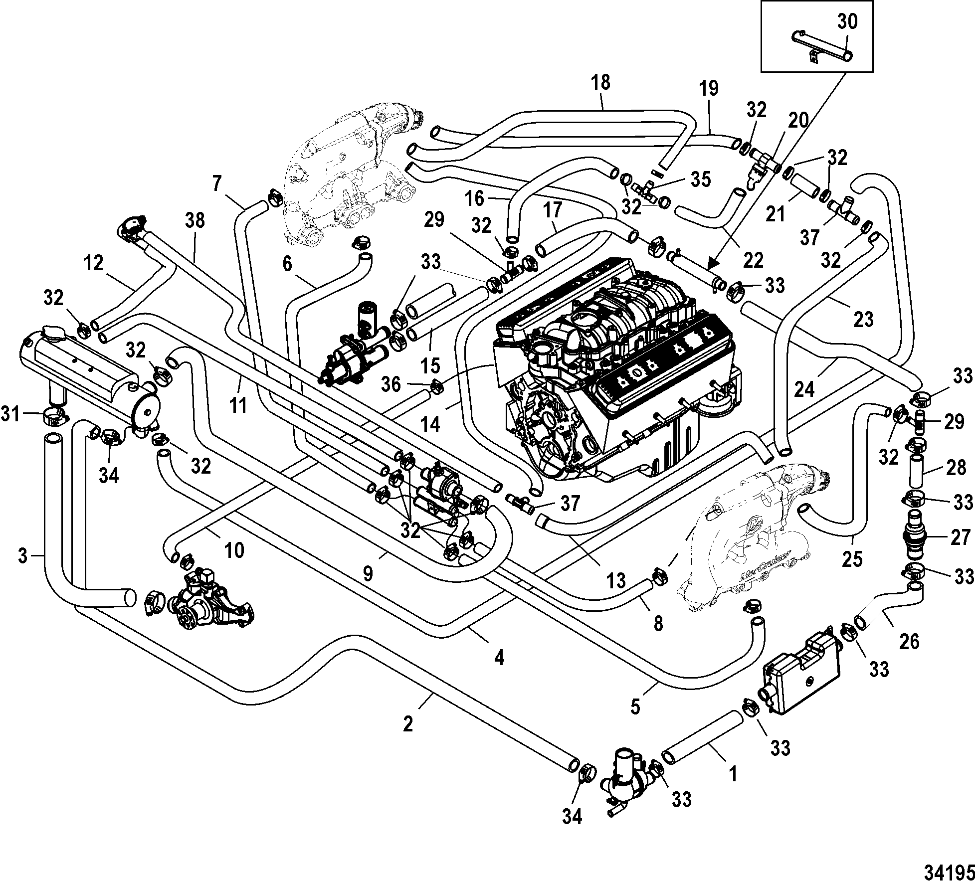
Diagram 7 4 Mercruiser Engine Cooling Diagram Mydiagram Online The cooling system in a 7.4 mercruiser engine plays a crucial role in preventing overheating and excessive wear on engine components. the diagram typically includes labels and symbols to identify components such as the heat exchanger, water pump, thermostat, hoses, and coolant passages. the 7.4 mercruiser cooling system diagram helps boat. Standard cooling system for mercruiser (7.4 l mpi bravo gen vi l29) engine start over different model > different engine section > standard cooling system reference numbers in this diagram can be found in a light blue row below — scroll down to order. Page 238: locating noisy lifters. 454 cid (7.4l) 502 cid (8.2l) service manual number 23 locating noisy lifters locate a noisy valve lifter by using a piece of garden hose approximately 4 ft (1.2 m) in length. place one end of hose near end of each intake and exhaust valve, with other end of hose to the ear. The cooling system in a mercruiser engine consists of several components, including the water pump, thermostat, heat exchanger, and circulating pump. understanding how these components work together to ensure proper coolant flow is crucial for troubleshooting and diagnosing potential problems. the flow of coolant begins with the water pump.

Mercruiser 7 4 Cooling System Diagram Huzaifaadley Page 238: locating noisy lifters. 454 cid (7.4l) 502 cid (8.2l) service manual number 23 locating noisy lifters locate a noisy valve lifter by using a piece of garden hose approximately 4 ft (1.2 m) in length. place one end of hose near end of each intake and exhaust valve, with other end of hose to the ear. The cooling system in a mercruiser engine consists of several components, including the water pump, thermostat, heat exchanger, and circulating pump. understanding how these components work together to ensure proper coolant flow is crucial for troubleshooting and diagnosing potential problems. the flow of coolant begins with the water pump. After break in period. ndations should be considered;use a propeller that allows the engine to operate at or near the top of the maximum rpm range (see “specifications” section) when at full th. ttle with a normal boat load.operation at 3 4 throttle s. tting or lower is recommended. refrain from prolonged operation. View and download mercruiser 454 magnum manual online. 7.4l 8.2l. 454 magnum engine pdf manual download. also for: 502 magnum.

Mercruiser Fresh Water Cooling System Diagram Headcontrolsystem After break in period. ndations should be considered;use a propeller that allows the engine to operate at or near the top of the maximum rpm range (see “specifications” section) when at full th. ttle with a normal boat load.operation at 3 4 throttle s. tting or lower is recommended. refrain from prolonged operation. View and download mercruiser 454 magnum manual online. 7.4l 8.2l. 454 magnum engine pdf manual download. also for: 502 magnum.

Diagram 7 4 Mercruiser Engine Cooling Diagram

Comments are closed.