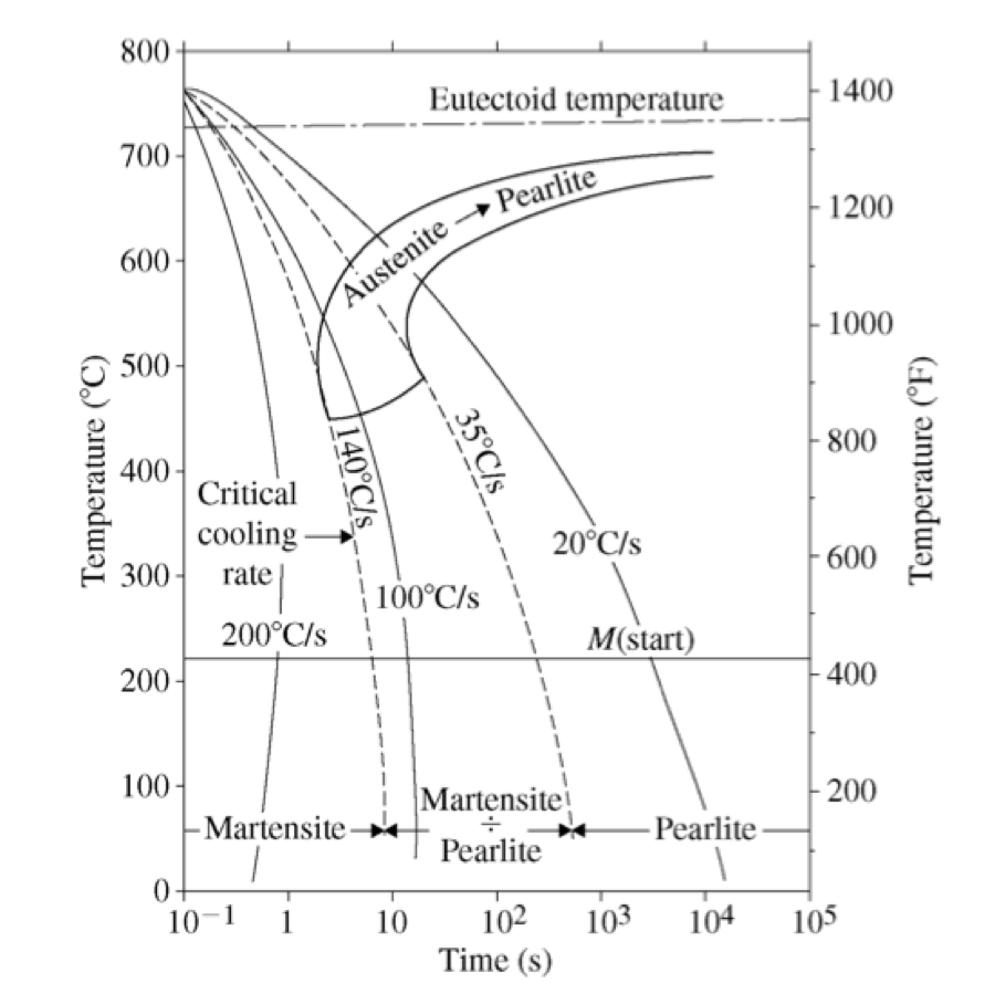
8 Continuous Cooling Transformation Diagram For The Plain Carbon Steel
8 Continuous Cooling Transformation Diagram For The Plain Carbon Steel Required to nucleate pearlite as per ttt diagram in fig. 8. but material has spent t 1 timing at higher than t 1 temperature in case of continuous cooling and incubation period at higher temperature is much more than t 1. the nucleation condition under continuous cooling can be explained by the concept of progressive nucleation theory of scheil. 17. Typical continuous cooling transformation diagrams using this method are shown in [1]. these diagrams allow the prediction of hardness and microstructure in the center of any diameter bar. this is also the most common method for displaying cct diagrams. figure 1: cct diagram for aisi 1060 steel. figure 2: cct diagram for aisi 5160 steel.

Schematic Illustration Of Continuous Cooling Transformation Cct Download scientific diagram | 8: continuous cooling transformation diagram for the plain carbon steel c1080 (from [86]). from publication: multiphase steels | das thema dieser arbeit ist die. Fig.4: time temperature transformation (schematic) diagram for plain carbon eutectoid steel t 1 t 2 t 3 t 4 t 5 m f, martensite finish temperature m 50, 50% martensite m s, martensite start temperature metastable austenite martensite martensite e 0 100 e log time hardness a e1 t 2 t 1 50% t t 2 1 pearlite fine pearlite upper bainite lower bainite. There are two main types of transformation diagram that are helpful in selecting the optimum steel and processing route to achieve a given set of properties. these are time temperature transformation (ttt) and continuous cooling transformation (cct) diagrams. cct diagrams are generally more appropriate for engineering applications as components. Continuous cooling transformation diagram of en s355 (astm a 572 grade 50, warranted yield stress 355 mpa) for welding (fast cooling, linear scale). a continuous cooling transformation (cct) phase diagram is often used when heat treating steel. [1] these diagrams are used to represent which types of phase changes will occur in a material as it.

Continuous Cooling Transformation Diagram There are two main types of transformation diagram that are helpful in selecting the optimum steel and processing route to achieve a given set of properties. these are time temperature transformation (ttt) and continuous cooling transformation (cct) diagrams. cct diagrams are generally more appropriate for engineering applications as components. Continuous cooling transformation diagram of en s355 (astm a 572 grade 50, warranted yield stress 355 mpa) for welding (fast cooling, linear scale). a continuous cooling transformation (cct) phase diagram is often used when heat treating steel. [1] these diagrams are used to represent which types of phase changes will occur in a material as it. The continuous cooling transformation diagram for 4340 steel (0.40 wt%c, 1.85 wt%ni, 0.80 wt%c, and 0.25 wt% mo). the presence of alloying elements other than carbon shift the pearlite (as well as the proeutectoid phase) and bainite formation to longer times, thus decreasing the critical cooling rate. Continuous cooling transformation (cct) diagrams are widely used when heat treating steels and represent which type of phase will occur in a material as it is cooled at different cooling rates. cct diagrams are constructed on the basis of dilatometry measurements on relatively small testing samples (cylindrical shape with diameter of 4mm and length of 11 mm in this study). the main aim of this.

Comments are closed.