Closed Loop Cooling Tower Diagram
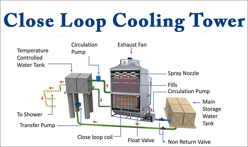
Close Loop Cooling Tower Hi Tech Equipments Closed circuit cooling towers, also known as evaporative fluid coolers, keep the system clean and contaminant free in a closed loop. this creates two separate fluid circuits: (1) an external circuit, in which spray water circulates over the coil and mixes with the outside air, and (2) an internal circuit, in which the process fluid to be cooled circulates inside the coil. Design capacity – 430.0 gpm design head – 47.0 feet motor size – 10 hp. less than anticipated pump headthe pump point shift has increased flow. over design to the order of 45%. cavitational and or tower vortex can occur unless. corrective measures are applied.the pump impeller diameter could, and should be cut down.
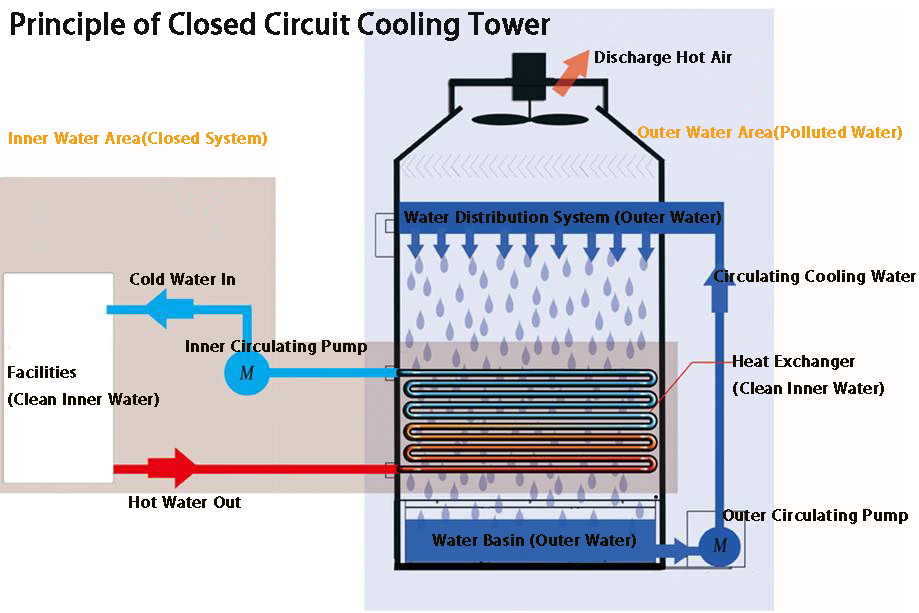
Principle Of Closed Circuit Cooling Tower Closed Circuit Cooling Tower More about closed circuit cooling towers. a closed circuit cooling tower, or dry cooling tower, involves no contact between the air and the fluid being cooled. this tower has two separate fluid circuits, one in which the fluid is recirculated on the outside of the second circuit, which is a bundle of tubes through which the hot water is flowing. Sequence of operation. when the operating fan(s) are operating at 50 percent speed, an additional fan shall be enabled and controlled at the same speed as the operating fans until all active cooling tower cell fans are enabled. when operating fans are running at minimum speed and the tower supply water temperature is five (5) degrees below the. The closed recirculating cooling water system evolved from methods used for the cooling of early engine designs. in a closed water system, water circulates in a closed cycle and is subjected to alternate cooling and heating without air contact. heat, absorbed by the water in the closed system, is normally transferred by a water to water. Series v benefits. low environmental impact. ` energy efficient. capacity is certified by the cooling technology institute using water, ethylene glycol, and propylene glycol. all units meet or exceed ashrae standard 90.1 energy eficiency requirements. closed loop cooling further minimizes process fouling, maintaining process eficiency.
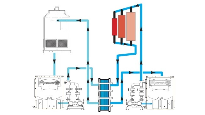
Closed Loop Cooling Tower Piping Schematic The closed recirculating cooling water system evolved from methods used for the cooling of early engine designs. in a closed water system, water circulates in a closed cycle and is subjected to alternate cooling and heating without air contact. heat, absorbed by the water in the closed system, is normally transferred by a water to water. Series v benefits. low environmental impact. ` energy efficient. capacity is certified by the cooling technology institute using water, ethylene glycol, and propylene glycol. all units meet or exceed ashrae standard 90.1 energy eficiency requirements. closed loop cooling further minimizes process fouling, maintaining process eficiency. Closed circuit cooling towers exploit the same physical principle as their open circuit counterpart in order to dissipate the heat: the forced evaporation of. Product: cooling towers – free cooling operation date: april 16, 2010 table of contents section page i. introduction background 2 ii. system design considerations: cooling tower selection 5 unit layout 6 cooling tower piping 7 cooling tower accessories 8 iii. capacity control methods 10.
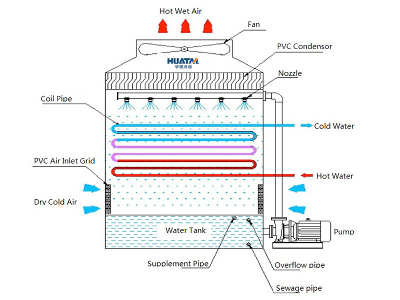
Closed Loop Cooling Tower Piping Schematic Closed circuit cooling towers exploit the same physical principle as their open circuit counterpart in order to dissipate the heat: the forced evaporation of. Product: cooling towers – free cooling operation date: april 16, 2010 table of contents section page i. introduction background 2 ii. system design considerations: cooling tower selection 5 unit layout 6 cooling tower piping 7 cooling tower accessories 8 iii. capacity control methods 10.
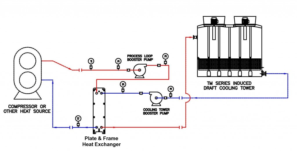
Closed Loop Cooling Tower Piping Schematic

Comments are closed.