Closed Loop Cooling Tower Piping Schematic
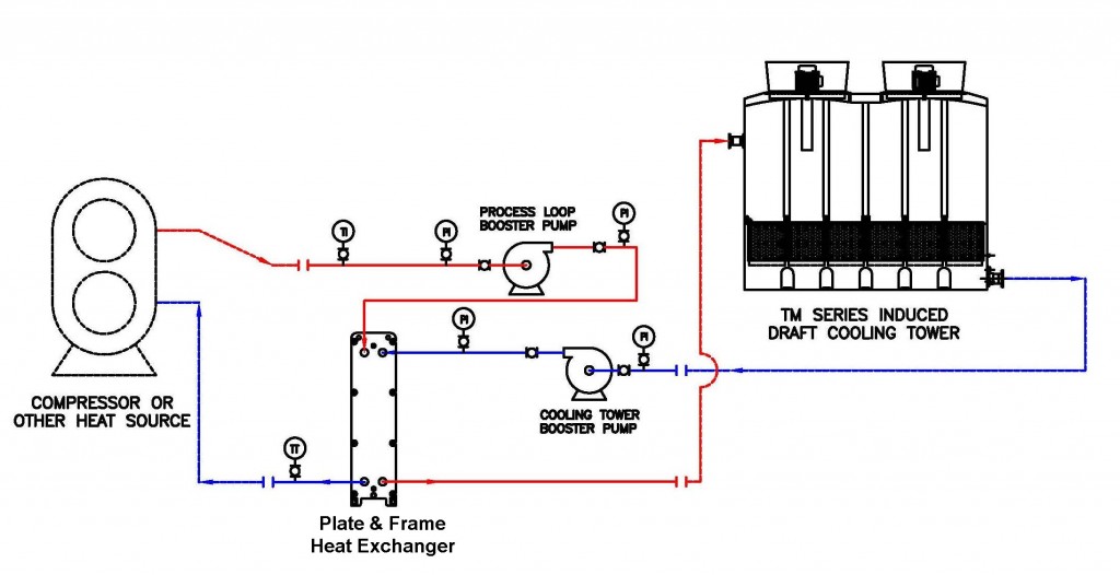
Closed Loop Cooling Tower Piping Schematic Design capacity – 430.0 gpm design head – 47.0 feet motor size – 10 hp. less than anticipated pump headthe pump point shift has increased flow. over design to the order of 45%. cavitational and or tower vortex can occur unless. corrective measures are applied.the pump impeller diameter could, and should be cut down. The cooling tower return pipework is installed to transport the warm water from the condenser side of the water cooled chiller to the cooling tower, with the flow being provided by the condenser water pumps that are installed on the supply side of the tower [tower to chiller] to move the water around the system. return pipework configuration.
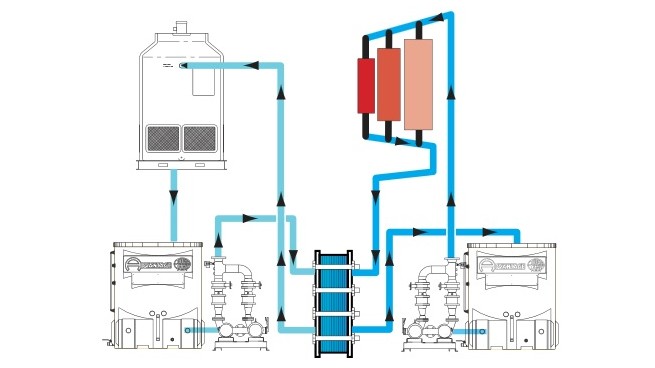
Closed Loop Cooling Tower Piping Schematic Closed loop technology. evapco’s wide range of closed circuit coolers, or simply “fluid coolers” provide a heat rejection alternative for engineers or end users who want (or need) to reduce water consumption and equipment maintenance, or a number of other considerations that exist with open loop cooling applications. Sequence of operation. when the operating fan(s) are operating at 50 percent speed, an additional fan shall be enabled and controlled at the same speed as the operating fans until all active cooling tower cell fans are enabled. when operating fans are running at minimum speed and the tower supply water temperature is five (5) degrees below the. Product: cooling towers – free cooling operation date: april 16, 2010 table of contents section page i. introduction background 2 ii. system design considerations: cooling tower selection 5 unit layout 6 cooling tower piping 7 cooling tower accessories 8 iii. capacity control methods 10. A closed loop cooling tower piping schematic is a diagram used to illustrate the components and flow of water through a closed loop system. it provides an overview of the entire system, as well as showing the connections between the different components. this type of schematic is particularly useful in cooling applications such as air.
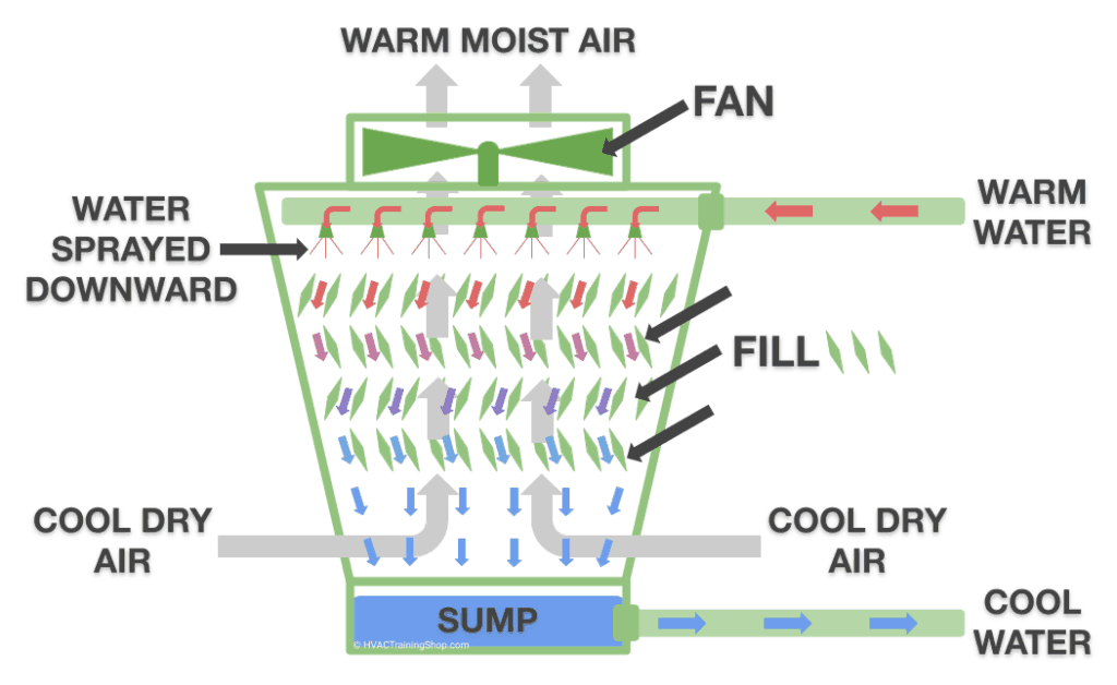
Closed Loop Cooling Tower Piping Schematic Product: cooling towers – free cooling operation date: april 16, 2010 table of contents section page i. introduction background 2 ii. system design considerations: cooling tower selection 5 unit layout 6 cooling tower piping 7 cooling tower accessories 8 iii. capacity control methods 10. A closed loop cooling tower piping schematic is a diagram used to illustrate the components and flow of water through a closed loop system. it provides an overview of the entire system, as well as showing the connections between the different components. this type of schematic is particularly useful in cooling applications such as air. The closed recirculating cooling water system evolved from methods used for the cooling of early engine designs. in a closed water system, water circulates in a closed cycle and is subjected to alternate cooling and heating without air contact. heat, absorbed by the water in the closed system, is normally transferred by a water to water. The "cooling tower" in your thread title got me thinking, like the previous responders, of a different type of closed loop cooling system that uses an unpressurized gravity cooling tower. in theory it should not matter where you put the pump in your pressurized closed loop system. when it comes to "best practices" two things come to mind.
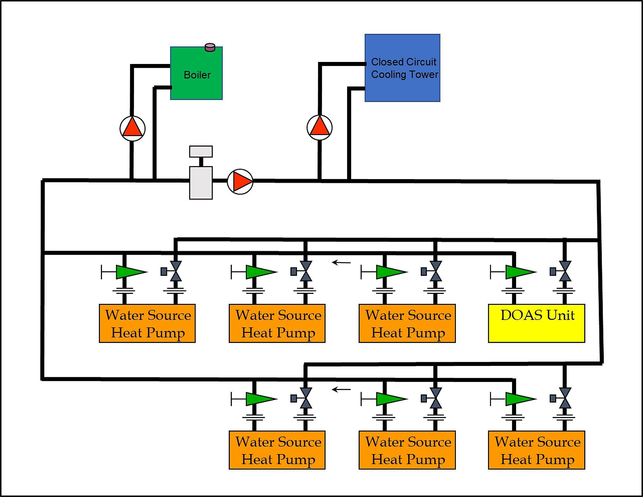
Closed Loop Cooling Tower Piping Schematic The closed recirculating cooling water system evolved from methods used for the cooling of early engine designs. in a closed water system, water circulates in a closed cycle and is subjected to alternate cooling and heating without air contact. heat, absorbed by the water in the closed system, is normally transferred by a water to water. The "cooling tower" in your thread title got me thinking, like the previous responders, of a different type of closed loop cooling system that uses an unpressurized gravity cooling tower. in theory it should not matter where you put the pump in your pressurized closed loop system. when it comes to "best practices" two things come to mind.
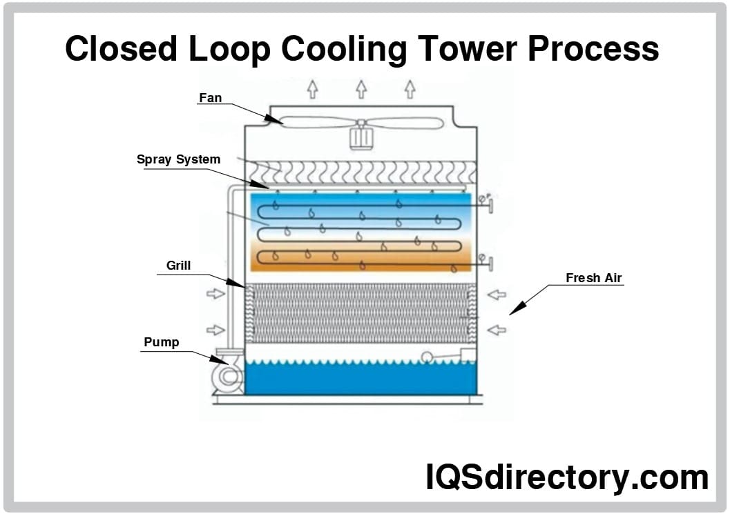
Closed Loop Cooling Tower System

Closed Loop Cooling Tower Piping Schematic Circuit Diagram

Comments are closed.