Construction Of Continuous Cooling Transformation Cct Diagram Lecture

Construction Of Continuous Cooling Transformation Cct Diagram Lecture Construction of continuous cooling transformation (cct) diagram lecture 3 part 1 heat treatment lecture series on heat treatmentplaylist for heat treatment c. Definition: stability of phases during continuous cooling of austenite. there are two types of cct diagrams. i) plot of (for each type of transformation) transformation start, specific fraction of transformation and transformation finish temperature against transformation time on each cooling curve.

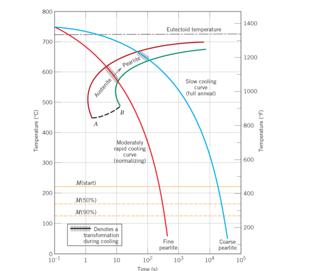
Schematic Illustration Of Continuous Cooling Transformation Cct The parent phase. continuous–cooling–transformation (cct) diagrams are then used to represent the evolution of microstructure (fig. 3). we shall illustrate cct diagrams using steels as an example, where the most important transformations are those that occur from austenite as the parent phase. the rate of transformation in a given steel. Cct diagrams measure the extent of transformation as a function of cooling time at continuously decreasing temperatures. the main difference from ttt diagrams is that continuous cooling does not allow for bainite formation and always results in pearlite. properties like hardness and strength depend on the formed microstructure constituents like. Typical continuous cooling transformation diagrams using this method are shown in [1]. these diagrams allow the prediction of hardness and microstructure in the center of any diameter bar. this is also the most common method for displaying cct diagrams. figure 1: cct diagram for aisi 1060 steel. figure 2: cct diagram for aisi 5160 steel. It diagram, 4340 steel (ni, cr, mn, mo as alloying elements) normally, bainite will not form (or will form to a small extent) during continuous cooling of plain carbon steels. by alloying, it becomes possible to obtain bainite phase upon continuous cooling continuous cooling transformation (cct) diagrams: effect of alloying.

Continuous Cooling Transformation Diagram Download Scientific Diagram Typical continuous cooling transformation diagrams using this method are shown in [1]. these diagrams allow the prediction of hardness and microstructure in the center of any diameter bar. this is also the most common method for displaying cct diagrams. figure 1: cct diagram for aisi 1060 steel. figure 2: cct diagram for aisi 5160 steel. It diagram, 4340 steel (ni, cr, mn, mo as alloying elements) normally, bainite will not form (or will form to a small extent) during continuous cooling of plain carbon steels. by alloying, it becomes possible to obtain bainite phase upon continuous cooling continuous cooling transformation (cct) diagrams: effect of alloying. The phase transformation behavior of a material can be displayed as a function of cooling rate on a continuous cooling transformation (cct) diagram [4]. cct diagrams can be used to predict the microstructures, and thus the properties, which would result from a specific cooling. Martensite transformation, c c t diagramprof. ratna kumar annabattula department of mechanical engineering iit madraseffect of cooling rate on the austenite.

Continuous Cooling Transformation Cct Diagrams Theme Route The phase transformation behavior of a material can be displayed as a function of cooling rate on a continuous cooling transformation (cct) diagram [4]. cct diagrams can be used to predict the microstructures, and thus the properties, which would result from a specific cooling. Martensite transformation, c c t diagramprof. ratna kumar annabattula department of mechanical engineering iit madraseffect of cooling rate on the austenite.

Continuous Cooling Transformation Diagram

Comments are closed.