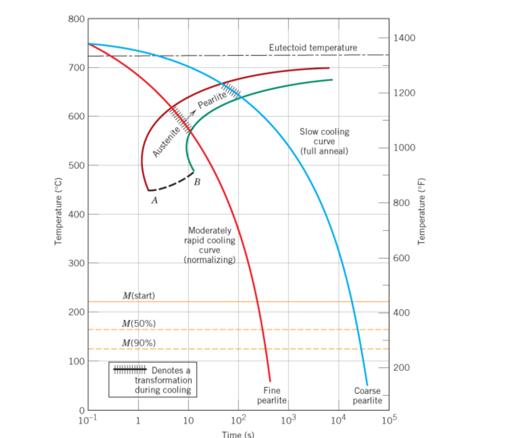
Continuous Cooling Transformation Diagram

Continuous Cooling Transformation Diagram Download Scientific Diagram Definition: stability of phases during continuous cooling of austenite. there are two types of cct diagrams. i) plot of (for each type of transformation) transformation start, specific fraction of transformation and transformation finish temperature against transformation time on each cooling curve. There are two types of continuous cooling diagrams drawn for practical purposes. type 1: this is the plot beginning with the transformation start point, cooling with a specific transformation fraction and ending with a transformation finish temperature for all products against transformation time for each cooling curve. type 2: this is the plot.

Continuous Cooling Transformation Diagram A continuous cooling transformation (cct) diagram is a useful tool that can be used with a thermal model for microstructure design and manufacturing process control. however, traditional cct diagrams are developed based on slow and monotonic cooling processes such as furnace cooling and air cooling, which are greatly different from the. Continuous cooling transformation (cct) diagrams are widely used when heat treating steels and represent which type of phase will occur in a material as it is cooled at different cooling rates. cct diagrams are constructed on the basis of dilatometry measurements on relatively small testing samples (cylindrical shape with diameter of 4mm and length of 11 mm in this study). the main aim of this. 1. introduction. to evaluate the performance of structural steels, understanding its microstructure after processing is crucial. the continuous cooling transformation (cct) diagram of a steel plays an important role in providing information on the steel microstructure, as the information includes the start temperatures of phase transformation during cooling, as well as hardness. There are two main types of transformation diagram that are helpful in selecting the optimum steel and processing route to achieve a given set of properties. these are time temperature transformation (ttt) and continuous cooling transformation (cct) diagrams. cct diagrams are generally more appropriate for engineering applications as components.

Schematic Illustration Of Continuous Cooling Transformation Cct 1. introduction. to evaluate the performance of structural steels, understanding its microstructure after processing is crucial. the continuous cooling transformation (cct) diagram of a steel plays an important role in providing information on the steel microstructure, as the information includes the start temperatures of phase transformation during cooling, as well as hardness. There are two main types of transformation diagram that are helpful in selecting the optimum steel and processing route to achieve a given set of properties. these are time temperature transformation (ttt) and continuous cooling transformation (cct) diagrams. cct diagrams are generally more appropriate for engineering applications as components. Isothermal and continuous cooling transformation (ct) diagrams help users map out diffusion controlled phase transformations of austenite to various mixtures of ferrite and cementite. this chapter discusses the application as well as limitations of these engineering tools in the context of heat treating eutectoid, hypoeutectoid, and. Continuous cooling transformation (cct) diagrams (see [147], [148], [188]) as the one presented in figure 8, illustrate the influence of cooling rate on the microstructural transformations.

Calculated Continuous Cooling Transformation Diagram Of Download Isothermal and continuous cooling transformation (ct) diagrams help users map out diffusion controlled phase transformations of austenite to various mixtures of ferrite and cementite. this chapter discusses the application as well as limitations of these engineering tools in the context of heat treating eutectoid, hypoeutectoid, and. Continuous cooling transformation (cct) diagrams (see [147], [148], [188]) as the one presented in figure 8, illustrate the influence of cooling rate on the microstructural transformations.

Continuous Cooling Transformation Curve Cct Of Duplex Stainless
8 Continuous Cooling Transformation Diagram For The Plain Carbon Steel

Comments are closed.