Continuous Cooling Transformation Diagram Explained вђ Theme Route

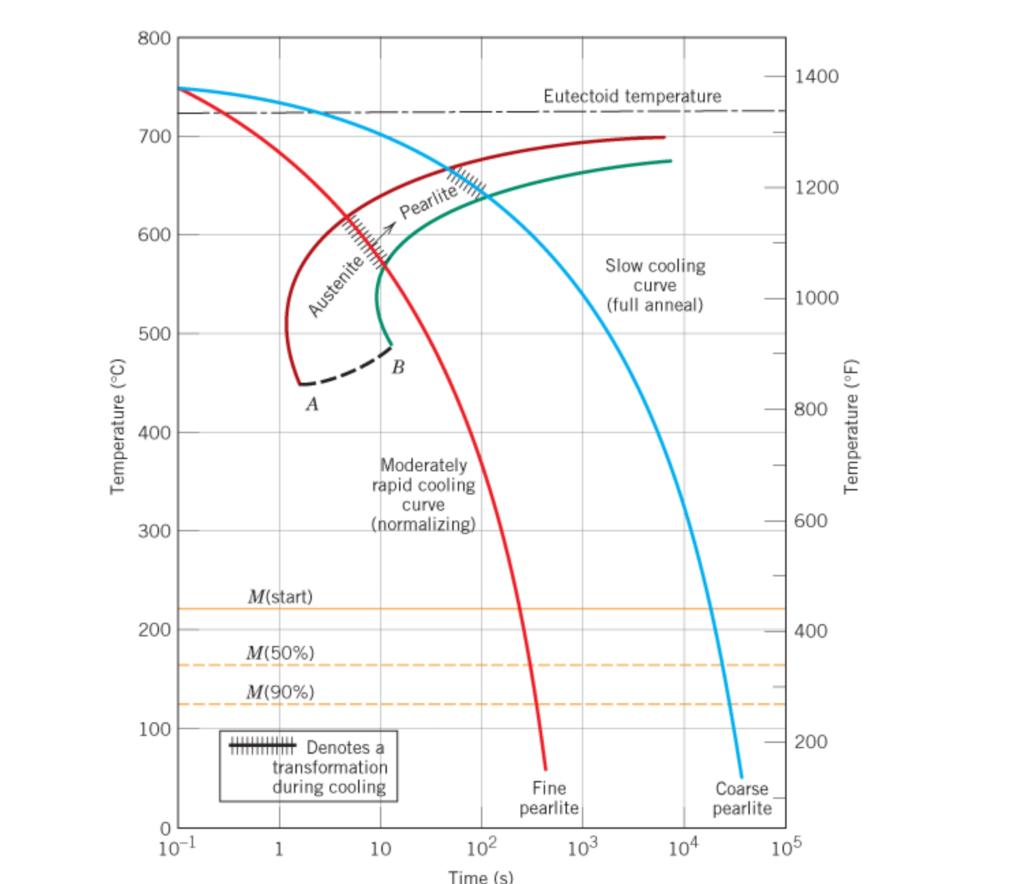
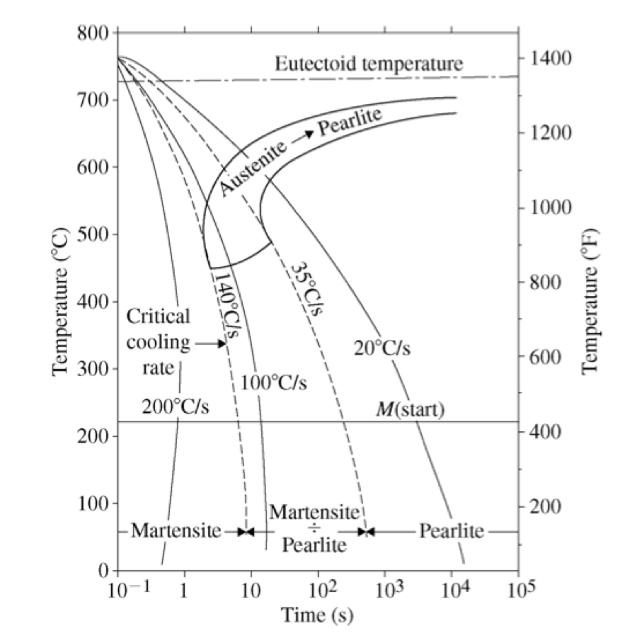
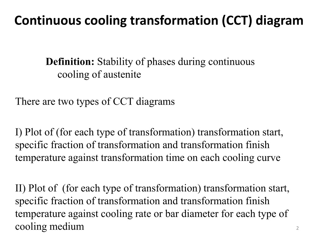
Continuous Cooling Transformation Diagram Theme Route Definition: stability of phases during continuous cooling of austenite. there are two types of cct diagrams. i) plot of (for each type of transformation) transformation start, specific fraction of transformation and transformation finish temperature against transformation time on each cooling curve. There are two types of continuous cooling diagrams drawn for practical purposes. type 1: this is the plot beginning with the transformation start point, cooling with a specific transformation fraction and ending with a transformation finish temperature for all products against transformation time for each cooling curve. type 2: this is the plot.

Continuous Cooling Transformation Diagram Explained Theme Route There are two main types of transformation diagram that are helpful in selecting the optimum steel and processing route to achieve a given set of properties. these are time temperature transformation (ttt) and continuous cooling transformation (cct) diagrams. cct diagrams are generally more appropriate for engineering applications as components. Typical continuous cooling transformation diagrams using this method are shown in [1]. these diagrams allow the prediction of hardness and microstructure in the center of any diameter bar. this is also the most common method for displaying cct diagrams. figure 1: cct diagram for aisi 1060 steel. figure 2: cct diagram for aisi 5160 steel. Hello guys,this is our new video on cct diagram explained in simplified way & it's applications.please go through our ttt diagram video before watching this. Cct diagram depends on composition of steel, nature of cooling, austenite grain size, extent of austenite homogenising, as well as austenitising temperature and time. 2. similar to ttt diagrams there are different regions for different transformation (i.e. cementite ferrite, pearlite, bainite and martensite).

Continuous Cooling Transformation Diagram Hello guys,this is our new video on cct diagram explained in simplified way & it's applications.please go through our ttt diagram video before watching this. Cct diagram depends on composition of steel, nature of cooling, austenite grain size, extent of austenite homogenising, as well as austenitising temperature and time. 2. similar to ttt diagrams there are different regions for different transformation (i.e. cementite ferrite, pearlite, bainite and martensite). Cct diagrams measure the extent of transformation as a function of cooling time at continuously decreasing temperatures. the main difference from ttt diagrams is that continuous cooling does not allow for bainite formation and always results in pearlite. properties like hardness and strength depend on the formed microstructure constituents like. The purpose of the present work is the implementation and validation of a model able to predict the microstructure changes and the mechanical properties in the modern high strength dual phase steels after the continuous annealing process line (capl) and galvanizing (galv) process. experimental continuous cooling transformation (cct) diagrams for 13 differently alloying dual phase steels were.

Ppt Continuous Cooling Transformation Cct Diagrams Powerpoint Cct diagrams measure the extent of transformation as a function of cooling time at continuously decreasing temperatures. the main difference from ttt diagrams is that continuous cooling does not allow for bainite formation and always results in pearlite. properties like hardness and strength depend on the formed microstructure constituents like. The purpose of the present work is the implementation and validation of a model able to predict the microstructure changes and the mechanical properties in the modern high strength dual phase steels after the continuous annealing process line (capl) and galvanizing (galv) process. experimental continuous cooling transformation (cct) diagrams for 13 differently alloying dual phase steels were.

Comments are closed.