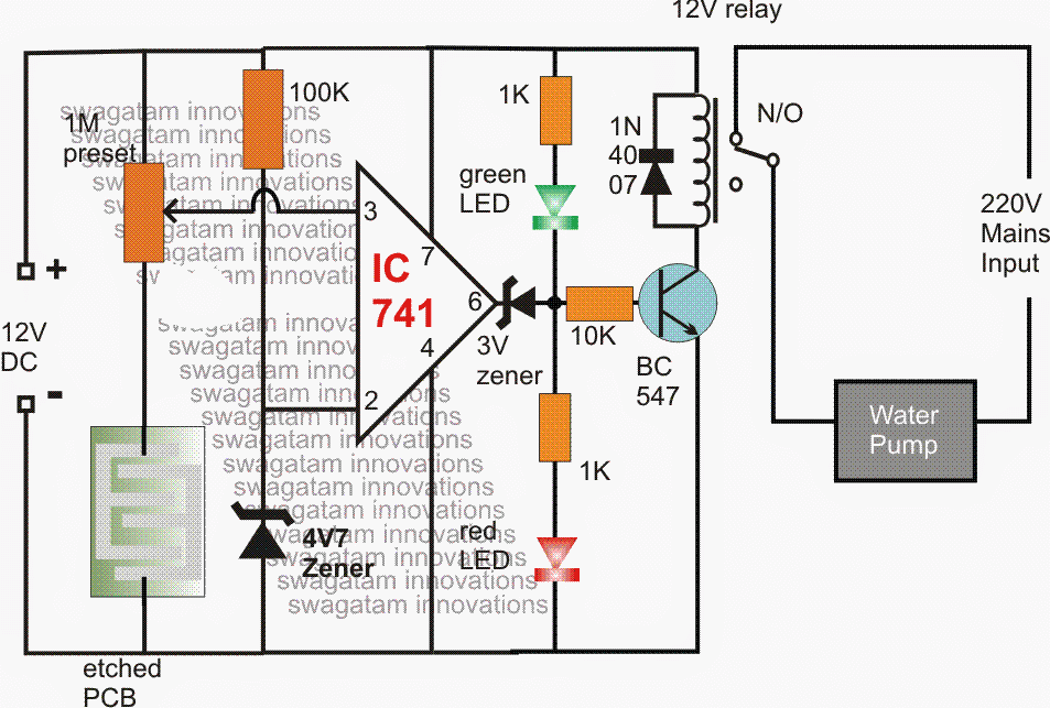
Cooler Circuit Diagram Wiring Diagram And Schematics

Cooler Circuit Diagram Wiring Diagram And Schematics Gather the necessary tools and materials. before starting the wiring process, make sure you have all the required tools and materials. this includes a screwdriver, wire strippers, electrical tape, wire nuts, and the evap cooler wiring diagram provided by the manufacturer. 2. turn off the power. 51 series 1000watt 48v wiring diagram. 52 series 300watt and 500watt 24v wire diagram. 52 series 1000watt wire diagram. hub series czhb basic. hub series czhb sport. hub series czhb sport x. visit the cruzin cooler website to see more information designed for a more technical service person to fix our coolers. check out wiring diagrams.

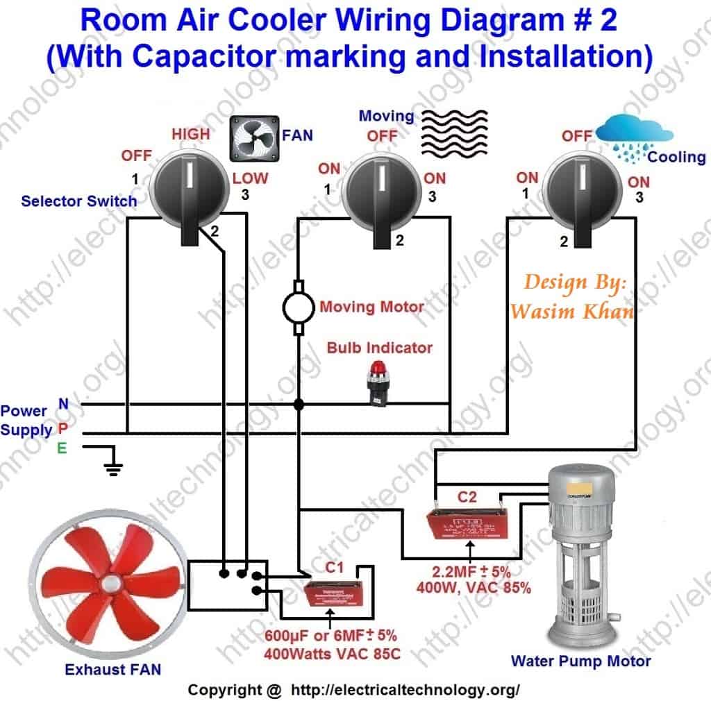
Room Air Cooler Wiring Diagram 2 With Capacitor Marking And Proper installation and wiring are essential for the optimal functioning of the evaporative cooler. the wiring diagram of an evaporative cooler includes various components that work together to ensure efficient cooling. these components include a motor, pump, thermostat, and junction box. the motor powers the fan, while the pump circulates. The air cooler schematic diagram can also help you figure out what kind of maintenance an air cooler needs. this includes a detailed overview of the various components and how each one functions and interacts with other components inside the air cooler. the diagram can also provide valuable information about the type of filters and cleaning. 3 pin and 4 pin fan wire diagrams. 3 pin fan connections. *cable coloring varies from fan to fan. pin name. color. color. color. color. 1. Here are some steps to wire a walk in cooler: 1. plan the electrical layout. before starting the wiring process, it is crucial to plan the electrical layout of the walk in cooler. this includes determining the location of the power source, the placement of outlets, switches, and any other electrical components.

Schematic Swamp Cooler Switch Wiring Diagram 3 pin and 4 pin fan wire diagrams. 3 pin fan connections. *cable coloring varies from fan to fan. pin name. color. color. color. color. 1. Here are some steps to wire a walk in cooler: 1. plan the electrical layout. before starting the wiring process, it is crucial to plan the electrical layout of the walk in cooler. this includes determining the location of the power source, the placement of outlets, switches, and any other electrical components. The wiring diagram will indicate which wire should be connected to the corresponding terminal. two speed motors: two speed motors offer more flexibility for controlling the speed of the evaporative cooler. these motors typically have three wires, labeled “high,” “medium,” and “low.”. the “high” wire is used for the highest speed. An evaporative cooler switch wiring diagram is a schematic that shows the various connections and components of a switch used in an evaporative cooler. this diagram helps electricians and technicians understand how the switch should be wired and connected to the cooler’s motor and power source.
Air Room Water Cooler Wiring Diagram The wiring diagram will indicate which wire should be connected to the corresponding terminal. two speed motors: two speed motors offer more flexibility for controlling the speed of the evaporative cooler. these motors typically have three wires, labeled “high,” “medium,” and “low.”. the “high” wire is used for the highest speed. An evaporative cooler switch wiring diagram is a schematic that shows the various connections and components of a switch used in an evaporative cooler. this diagram helps electricians and technicians understand how the switch should be wired and connected to the cooler’s motor and power source.

4 Wire Cooler Motor Wiring Diagram And Connection Procedure Etechnog

Cooler Circuit Diagram Wiring Diagram And Schematics

Comments are closed.