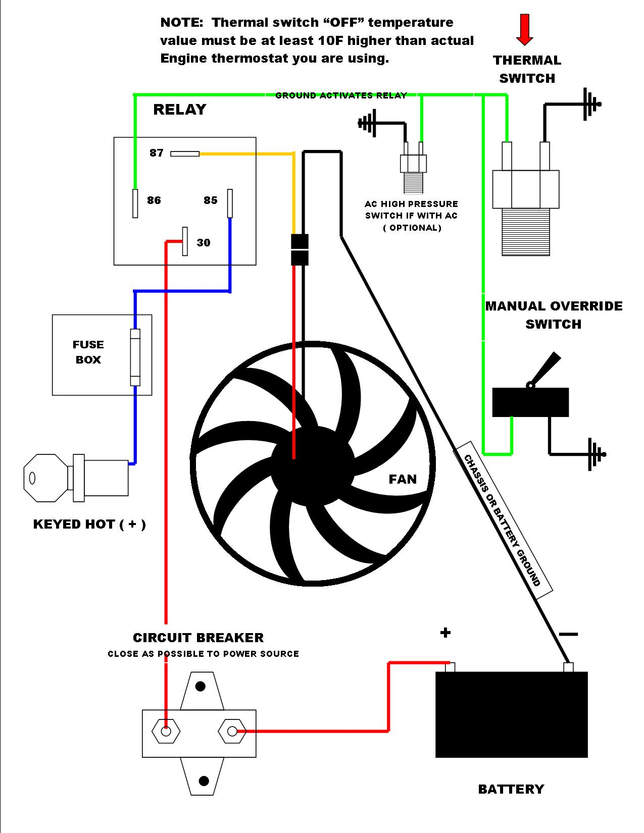
Cooling Fan Resistor Diagram

2007 Uplander Cooling Fan Resistor Wiring Diagram Learn how to locate, remove, and install a cooling fan resistor on your vehicle. a cooling fan resistor controls the speed of the fan motor and can cause engine overheating or fan failure if broken. The descriptions of cooling fan operation contained in this procedure are based on the factory electrical diagrams, the troubleshooting experience of other 944 owners, and my own experience. cooling fan operation of pre 1985.5 944s with air conditioning. on early 944s equipped with air conditioning, there are two electric cooling fans.

2007 Uplander Cooling Fan Resistor Wiring Diagram 1. engine overheats. one of the first symptoms of a potential problem with the cooling fan resistor is engine overheating. if the cooling fan resistor fails or has any issues, it can cause power to be cut off from the cooling fans, which can lead to overheating. any sort of overheating issue should be tended to as soon as possible to avoid the. Mini r53 models utilize an electronic cooling fan integrated into the cooling fan shroud. there is a resistor in the wiring and attached to the shroud that will control the speed of the fan. if your fan only runs at high speed when it is on it is probably the resistor that has failed. With two fans, there is no resistor but the second fan is 'used' as resistor, resulting in half the speed off both fans. but with two fans you can create three kind off air speeds. 1 = low: both fans on half the power, creating little air flow. 2 = medium: one fan at full speed, creating bit more air flow than low speed. Member. may 17, 2017. #1. this modification will allow low speed fan operation at a lower than stock temperature, without setting any codes. this is a 3 speed fan, with two resistors built into the fan motor itself, to limit motor current on the two lower speeds. there are a total of five fan control relays.

Cooling Fan Circuit Diagram With two fans, there is no resistor but the second fan is 'used' as resistor, resulting in half the speed off both fans. but with two fans you can create three kind off air speeds. 1 = low: both fans on half the power, creating little air flow. 2 = medium: one fan at full speed, creating bit more air flow than low speed. Member. may 17, 2017. #1. this modification will allow low speed fan operation at a lower than stock temperature, without setting any codes. this is a 3 speed fan, with two resistors built into the fan motor itself, to limit motor current on the two lower speeds. there are a total of five fan control relays. Step 1 – clean any debris. before beginning diagnosis for a faulty cooling fan, ensure the fan and radiator are free of excessive dirt, mud, or debris. many jk owners regularly take their wrangler off road and often drive through some rugged terrain. unfortunately, while the wrangler can traverse heavy mud, deep water, and sandy dusty trails. Replacing the resistor with a new one (yellow arrow) is simple even if you are working on wiring for the first time. use a 10mm socket and remove the two bolts holding the resistor and cover to the shroud (red arrows). slide the resistor out from the shroud and pop open the cover protecting the wiring (red arrow).

Electric Cooling Fan Diagram Step 1 – clean any debris. before beginning diagnosis for a faulty cooling fan, ensure the fan and radiator are free of excessive dirt, mud, or debris. many jk owners regularly take their wrangler off road and often drive through some rugged terrain. unfortunately, while the wrangler can traverse heavy mud, deep water, and sandy dusty trails. Replacing the resistor with a new one (yellow arrow) is simple even if you are working on wiring for the first time. use a 10mm socket and remove the two bolts holding the resistor and cover to the shroud (red arrows). slide the resistor out from the shroud and pop open the cover protecting the wiring (red arrow).

Pelican Technical Article Mini R53 Cooling Fan Resistor Replacement

Comments are closed.