Cooling Hook Up On The X2 With Pics And Diagram
Cooling Hook Up On The X2 With Pics And Diagram Re: cooling hook up on the x2 with pics and diagram the way ttts drew it up will definately work , the lower fitting on the westcoast pipe is feeding the chambe sonic wave. the way you drew it is fine but id make the straight through of the "t" goto the head pipe and the 90 degree off the "t" goto the fitting feeding the chamber sonic wave. Re: cooling hook up on the x2 with pics and diagram it will have a spot to put powervalves but the x2 is a tight squeeze and so i will not be using powervalves. the two lameys at my house , one has powervalves and one doesnt , to me its hard to tell the difference in power. to me its mostly in the smooth power and more even pull with the.

Electric Cooling Fan Control Wiring Diagram Search in titles only search in kawasaki x2 only. search. advanced search. Oct 8, 2013. #2. bare with me here, this is a 650 sx with kirker pipe, single cooling. i looked at some coffmans for the x2 on ebay and they have the same cooling fittings & cooling set up as this. the sx has two thru hull tubes, one of these two dumps to pump area but does not connect to the pump, i cap this tube off at the bulk head. See 2nd & 3rd pic. the heat exchanger's top hose (#2) in the diagram below (see pic #6) is the outlet from the heat exchanger and return line to the transmission. this line was intercepted to t stat and the inlet to the cooler. the cooler return line goes back to the heat exchanger return line back to transmission. Emergency heat is when you are using only heat strips for heat. the aux. heat indication, lets you know that some of the heat strips are coming on in tandem along with the heat pump when the heat pump alone can't keep up with heat demand due to low outdoor temps. i'm pretty sure the x2 on the trane stat is for the emerg.

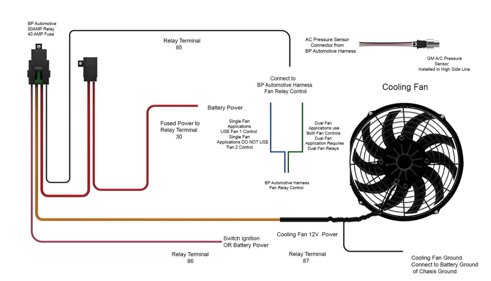
2008 Jaguar Cooling Wiring Diagram See 2nd & 3rd pic. the heat exchanger's top hose (#2) in the diagram below (see pic #6) is the outlet from the heat exchanger and return line to the transmission. this line was intercepted to t stat and the inlet to the cooler. the cooler return line goes back to the heat exchanger return line back to transmission. Emergency heat is when you are using only heat strips for heat. the aux. heat indication, lets you know that some of the heat strips are coming on in tandem along with the heat pump when the heat pump alone can't keep up with heat demand due to low outdoor temps. i'm pretty sure the x2 on the trane stat is for the emerg. You won't physically need the x2 underhood, x105, x111, x115, x125 connectors when its all done, but these connectors contain all the wires you will need to hook up to a new fuse block, run to your gas pedal, diagnostic port, control a fan, fuel pump, so on. pins highlighted in yellow at the ecm have been removed and pulled back. Start your wiring project by taking both of the positive wires from the fans and run them to the yellow wires on each relay (tab 87). then connect switched power (usually from your ignition switch), to the blue wires on both relays (tab 86). next, splice together both black wires from the relays (tab 85) and connect them to the thermostat switch.

Nomadic Cooling X2 Specs Chart Vanlife Outfitters You won't physically need the x2 underhood, x105, x111, x115, x125 connectors when its all done, but these connectors contain all the wires you will need to hook up to a new fuse block, run to your gas pedal, diagnostic port, control a fan, fuel pump, so on. pins highlighted in yellow at the ecm have been removed and pulled back. Start your wiring project by taking both of the positive wires from the fans and run them to the yellow wires on each relay (tab 87). then connect switched power (usually from your ignition switch), to the blue wires on both relays (tab 86). next, splice together both black wires from the relays (tab 85) and connect them to the thermostat switch.

Electric Cooling Fan Diagram

Comments are closed.