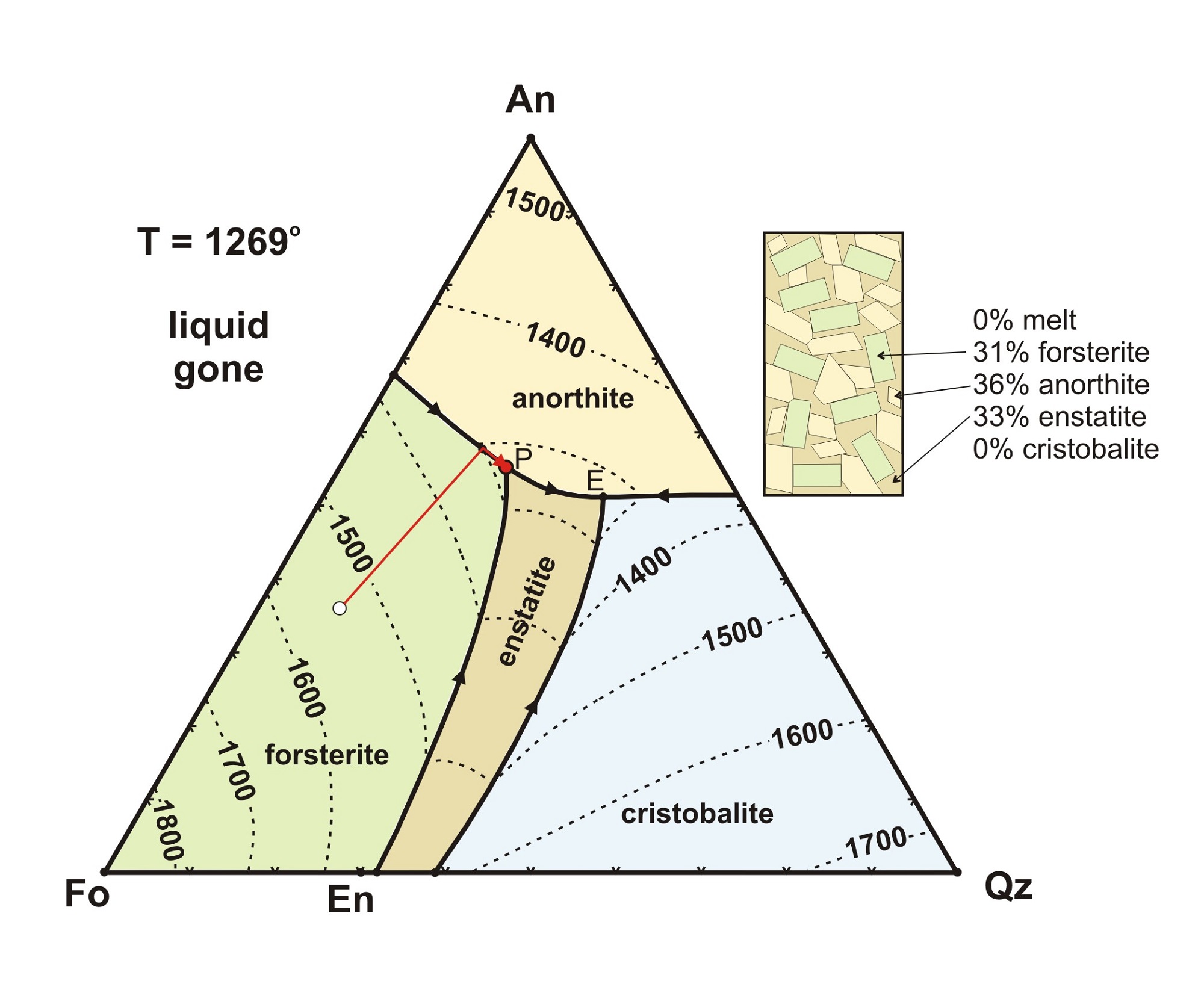
Cooling On A Ternary Phase Diagram

Ternary Phase Diagrams 101 Diagrams T = 650 ° liq c a b. t < 650 ° c a b (all solid) at any temperature an isothermal plane can be constructed through the system that will show the phases present for all compositions in the ternary system. such an isothermal plane for the system abc at 700 ° is shown in figure 4. ii. Phase diagram and “degrees of freedom”. phase diagrams is a type of graph used to show the equilibrium conditions between the thermodynamically distinct phases; or to show what phases are present in the material system at various t, p, and compositions. “equilibrium” is important: phase diagrams are determined by using slow cooling.

Cooling Path In A Ternary Phase Diagram вђ Bilarasa Space model for a simple eutectic ternary system a b c. mech 6661 lecture 11 3. alkemade lines. • alkemade lines are the lines that c connect the primary compositions of two phase fields which share a common boundary. • alkemade lines divide a phase c diagram into compatibility triangles. • this diagram is divided into two compatibility. For any three phase assemblage, more than one corner of the three phase triangle may change composition upon heating or cooling. the lowest possible temperature for which a liquid can exist may be a ternary minimum, the bottom of a single trough like cotectic curve. • horizontal, isothermal sections through a three dimensional ternary. We will limit our discussion of phase diagrams of multi component systems to binary alloys and will assume pressure to be constant at one atmosphere. phase diagrams for materials with more than two components are complex and difficult to represent. an example of a phase diagram for a ternary alloy is shown for a fixed t and p below. Vertical sections. vertical sections (sometimes known as isopleths) are sections taken through a ternary phase diagram that are perpendicular to the plane of the composition triangle. they are rectangular with a horizontal composition axis (showing a series of compositions that plot on a straight line in ternary composition space) and a.

вђњpark Cooling Serviceвђќ Ternary Phase Diagram Cooling Effect We will limit our discussion of phase diagrams of multi component systems to binary alloys and will assume pressure to be constant at one atmosphere. phase diagrams for materials with more than two components are complex and difficult to represent. an example of a phase diagram for a ternary alloy is shown for a fixed t and p below. Vertical sections. vertical sections (sometimes known as isopleths) are sections taken through a ternary phase diagram that are perpendicular to the plane of the composition triangle. they are rectangular with a horizontal composition axis (showing a series of compositions that plot on a straight line in ternary composition space) and a. Starting from the very basics of phase diagrams and phase equilibria we will go through reading unary, binary and ternary phase diagrams, including liquidus projections, isothermal and vertical phase diagram sections. application examples are directly derived from these phase diagrams of fe, cu ni, mg al, and mg al zn. Note that the alkemade line for equilibrium between xy and w, crosses the boundary curve where xy, w and liquid coexist. thus, the down temperature direction points toward the bottom of the diagram for all liquids below the xy w join, and towards the top of the diagram for all liquids on the boundary curve above the xy w join.

Comments are closed.