Cooling System Mercury Outboard Water Flow Diagram Headcontrolsystem

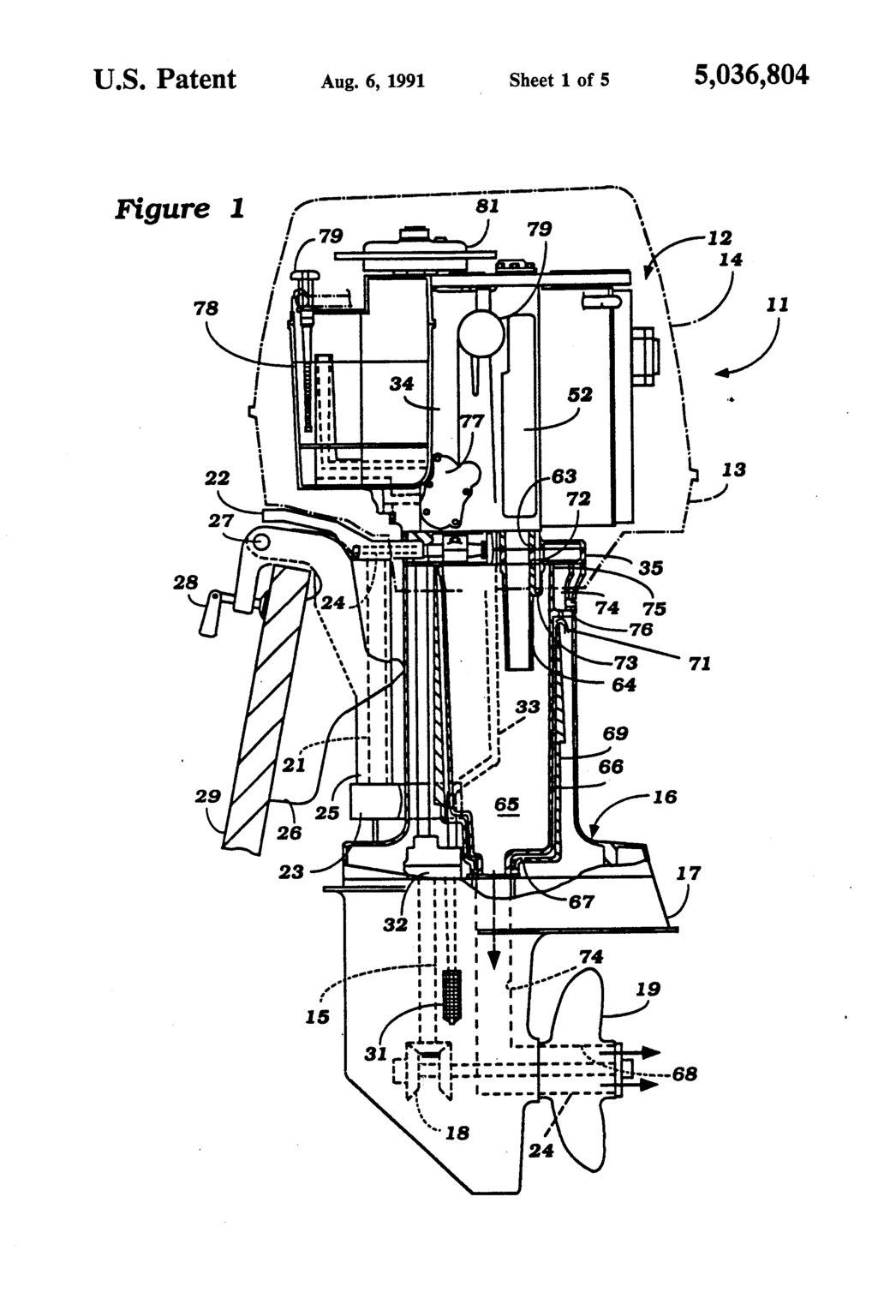
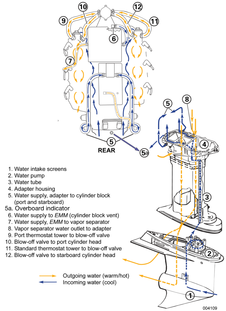
Cooling System Mercury Outboard Water Flow Diagram Headcontrolsystem The cooling system in a mercury outboard motor is a critical component that plays a vital role in maintaining the engine’s optimal operating temperature. it is essential for the proper functioning and longevity of the motor. without a properly functioning cooling system, the engine can overheat, leading to severe damage and potential breakdowns. In this article, we will explore the water flow diagram of the cooling system in a mercury outboard motor. the cooling system in a mercury outboard motor consists of several key components that work together to keep the engine cool. these components include the water pump, thermostat, temperature switch, and various hoses and passages.

Mercury Outboard Cooling System Diagram Headcontrolsystem The cooling system on an outboard is a very simple and compact application. water is inducted through the lower unit by a water pump impeller, and then forced upward to circulate throughout the powerhead, and eventually exits through the exhaust system. there are a couple of things pertaining to the outboard cooling system that need regular. Aug 25, 2005. messages. 68. apr 29, 2018. #1. please direct me to a water flow diagram for my 2.0l v6 serial c110740. hard time finding correct diagram online. i need a definitive answer to where the thermostat is located in my cooling system. water telltale isn't running when i start up this new to me engine. New member. i have a 2010 9.9 merc. i noticed "no flow" out from the outflow hole that last time i was out. the. impeller has never been replaced, so, i ordered a new impeller repair kit. after removing the lower. unit, the impeller and gasket seem to look fine. there is nothing blocking the flow, the key was in place to the impeller was turning. Hey there dangar stu here. today's video is about the path that the cooling water takes through an outboard power head, and is proudly sponsored by marineengine . i think most people are pretty familiar with the path the cooling water takes from the leg down those side grills up into the water pump, through the impeller then up the water.

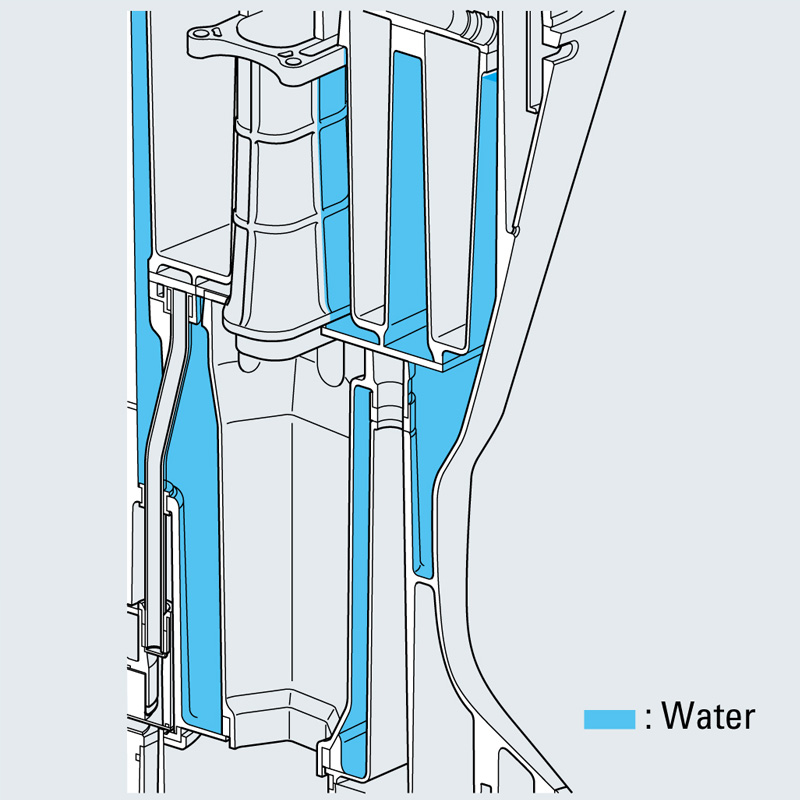
An Illustrated Guide To The Water Flow Diagram In Mercury Outboard New member. i have a 2010 9.9 merc. i noticed "no flow" out from the outflow hole that last time i was out. the. impeller has never been replaced, so, i ordered a new impeller repair kit. after removing the lower. unit, the impeller and gasket seem to look fine. there is nothing blocking the flow, the key was in place to the impeller was turning. Hey there dangar stu here. today's video is about the path that the cooling water takes through an outboard power head, and is proudly sponsored by marineengine . i think most people are pretty familiar with the path the cooling water takes from the leg down those side grills up into the water pump, through the impeller then up the water. 29. mar 25, 2003. #4. re: cooling water flow in outboard ***. cooling systems are going to be different for make and size configuration.there is multiple cooling paths in your v 6's.my mercs have a pressure relief valve thatopens & allows water to the center of block and exhaust plate,the heads each have a thermo that opens on temp. (143)i am. 10 water tube. 11 wall of water – if water level height is insufficient, water pump may draw in air resulting in an overheated engine. 12 check valve for powerhead flush. 13 excess water from wall of water around exhaust bucket exits around anodes. 90 855347r1 january 1999.

Cooling System Mercury Outboard Water Flow Diagram Headcontrolsystem 29. mar 25, 2003. #4. re: cooling water flow in outboard ***. cooling systems are going to be different for make and size configuration.there is multiple cooling paths in your v 6's.my mercs have a pressure relief valve thatopens & allows water to the center of block and exhaust plate,the heads each have a thermo that opens on temp. (143)i am. 10 water tube. 11 wall of water – if water level height is insufficient, water pump may draw in air resulting in an overheated engine. 12 check valve for powerhead flush. 13 excess water from wall of water around exhaust bucket exits around anodes. 90 855347r1 january 1999.

Comments are closed.