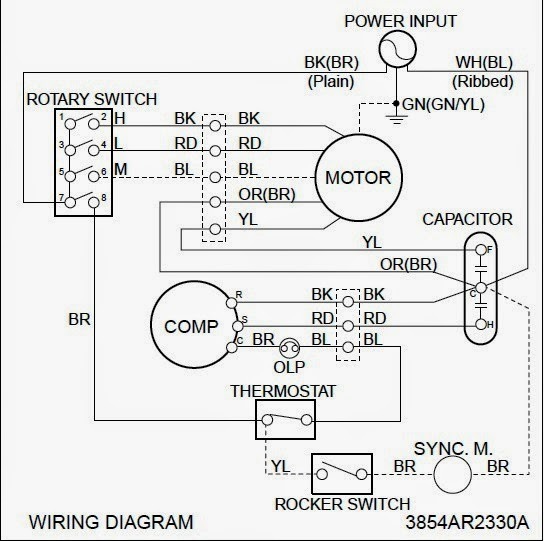
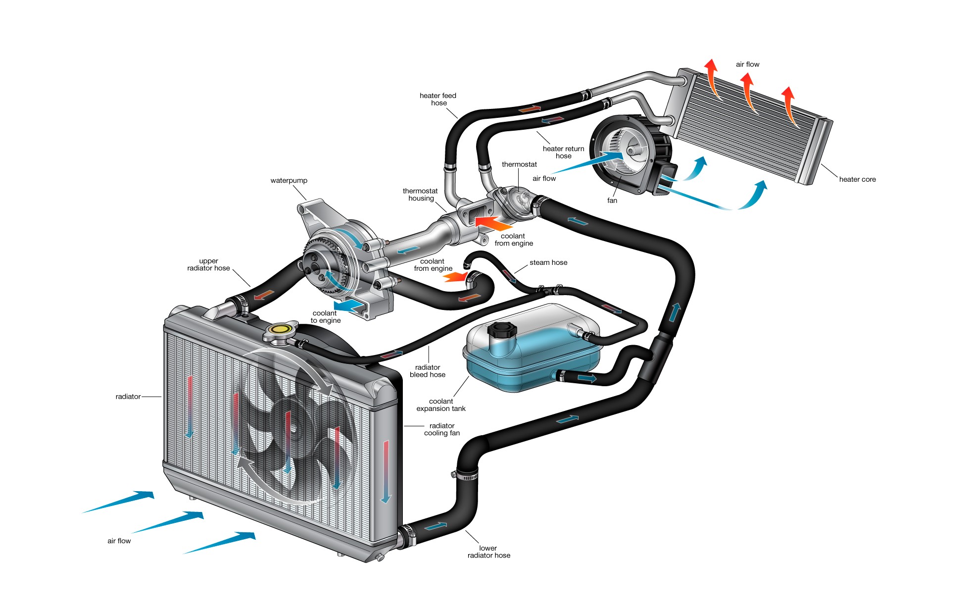
Cooling System Wiring Diagram

Hvac Wiring Explained These control the power, heat and fan. standard thermostats use 4 or 5 wires: r, w, g, y, and sometimes c. these control the power, heat, fan, and cooling. more advanced thermostats use 6 8 wires. the extra wires control additional hvac system features and settings, signaling a two stage cooling or heat pump system. Here’s how to wire a thermostat using the color code and, fyi, each terminal’s purpose. attach the red wire to the r terminal (call for heating and or cooling). attach the green wire to the g terminal (fan). attach the white wire to the w terminal (heat). attach the yellow wire to the y terminal (ac).

Cooling Fan Power Wire At Michael Harmon Blog Wiring diagrams are essentially blueprints that depict the electrical connections and functions of the various components in an hvac system. they include details such as the locations of switches, transformers, motors, capacitors, and relays, as well as how these components are wired together. by studying these diagrams, technicians can. Consult your owners install guide for wiring examples and systems compatible with your thermostat*. the thermostat uses one wire to control the primary functions of your hvac system, such as heating, cooling, and fan. see the diagram below for the role of each wire in your system: s – indoor and outdoor wired sensors. The hvac wiring diagram thermostat illustrates the electrical connections between the thermostat, the heating or cooling system, and the power supply. it shows the different wires and terminals involved in the system and their corresponding functions. the diagram provides a visual representation of how the thermostat interacts with the hvac. A new system may need as many as ten wires (like a two stage heat, two stage cooling system, heat pump reversing valves, fan control, etc.) if the system had two stage heating, and or cooling, the 2nd stage termainals would be labelled w1 and w2 for heating, y1 and y2 for cooling. these additional terminals are not shown in this diagram.

Coolant System Diagram My Wiring Diagram The hvac wiring diagram thermostat illustrates the electrical connections between the thermostat, the heating or cooling system, and the power supply. it shows the different wires and terminals involved in the system and their corresponding functions. the diagram provides a visual representation of how the thermostat interacts with the hvac. A new system may need as many as ten wires (like a two stage heat, two stage cooling system, heat pump reversing valves, fan control, etc.) if the system had two stage heating, and or cooling, the 2nd stage termainals would be labelled w1 and w2 for heating, y1 and y2 for cooling. these additional terminals are not shown in this diagram. Green. g. fan. here are the connections to be made when wiring a 4 wire thermostat: white wire to the w terminal for heating. red wire to the r terminal for 24v power from the transformer in the furnace or air handler – or rc on some thermostats. yellow wire to the y terminal for cooling. green wire to the g terminal for indoor fan or fans. In hvac wiring diagrams, the symbol for the power supply represents the electrical source that provides the necessary energy to operate the heating, ventilation, and air conditioning system. this symbol typically consists of a straight line with a small circle at the end, indicating the connection point to the power source.

Cooling Fans Wiring Diagram Youtube Green. g. fan. here are the connections to be made when wiring a 4 wire thermostat: white wire to the w terminal for heating. red wire to the r terminal for 24v power from the transformer in the furnace or air handler – or rc on some thermostats. yellow wire to the y terminal for cooling. green wire to the g terminal for indoor fan or fans. In hvac wiring diagrams, the symbol for the power supply represents the electrical source that provides the necessary energy to operate the heating, ventilation, and air conditioning system. this symbol typically consists of a straight line with a small circle at the end, indicating the connection point to the power source.

Basic Air Conditioning Wiring Diagram

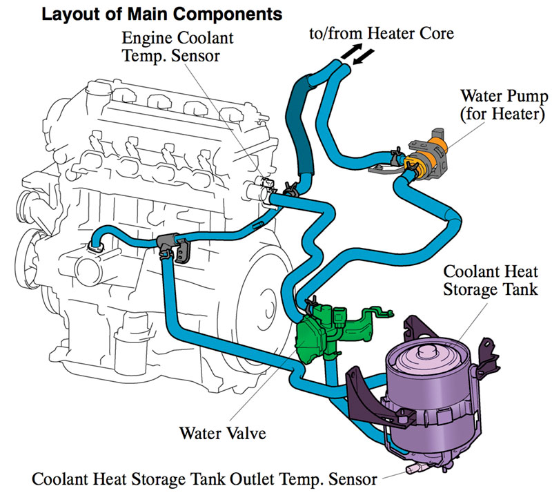
Mastering The Gen 2 Prius Engine Cooling System Automotive Tech Info

Comments are closed.