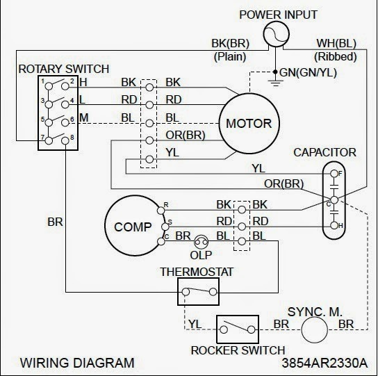
Cooling System Wiring Diagram Circuit Diagram

Basic Air Conditioning Wiring Diagram The diagram provides a detailed layout of the system’s electrical circuit, indicating how the components are connected and the path of the electrical current. the purpose of hvac wiring diagrams is to provide a visual guide for technicians to follow when installing or servicing the system. Hvac wiring diagram and legend. we’ll jump right into showing you a schematic diagram for a simple air conditioning unit. we’ll make a ladder diagram using a simple air conditioner as our example. first we have the main electrical supply lines l1 and l2 providing 208 230 volt, single phase power. then we’ll need a transformer to provide.

Hvac Wiring Explained 1 importance of electrical wiring for air conditioning systems. in the detailed design phase, the electrical designer must size and select the wires cables, conduits, starters, disconnects and switchgear necessary for supplying power and control to hvac equipment. this information designed by the electrical designer will be and must appear on. In hvac wiring diagrams, the symbol for the power supply represents the electrical source that provides the necessary energy to operate the heating, ventilation, and air conditioning system. this symbol typically consists of a straight line with a small circle at the end, indicating the connection point to the power source. Remove the existing thermostat cover. match the wires: connect the r wire from the heat pump to the r terminal on the thermostat. connect the y wire to the y terminal, which usually controls cooling. connect the g wire to the g terminal for the fan. secure connections with wire connectors, ensuring no exposed copper is visible. These control the power, heat and fan. standard thermostats use 4 or 5 wires: r, w, g, y, and sometimes c. these control the power, heat, fan, and cooling. more advanced thermostats use 6 8 wires. the extra wires control additional hvac system features and settings, signaling a two stage cooling or heat pump system.
Engine Cooling Fan Wiring Diagram Circuit Diagram Remove the existing thermostat cover. match the wires: connect the r wire from the heat pump to the r terminal on the thermostat. connect the y wire to the y terminal, which usually controls cooling. connect the g wire to the g terminal for the fan. secure connections with wire connectors, ensuring no exposed copper is visible. These control the power, heat and fan. standard thermostats use 4 or 5 wires: r, w, g, y, and sometimes c. these control the power, heat, fan, and cooling. more advanced thermostats use 6 8 wires. the extra wires control additional hvac system features and settings, signaling a two stage cooling or heat pump system. A schematic symbols chart provides a visual representation of the different components and devices used in hvac systems. these symbols help hvac technicians and engineers easily interpret and create schematic diagrams for system design, troubleshooting, and maintenance. the hvac schematic symbols chart includes symbols for various components. Ladder, line, and installation schematics. hvac system diagrams and schematics fall into three different categories: ladder, line, and installation diagrams. here’s how those break down. ladder diagrams. the ladder diagram is one of the easier ones to read. it lists the circuit connections and electrical wiring for the system.

Comments are closed.