Define Reference Plane In Engineering Drawing

Engineering Drawing Line Inclined To Both The Reference Planes Youtube A datum is a plane, a straight line, or a point that is used as a reference when processing a material or measuring the dimensions of a target. iso definition; types of datums; drawing indications of datum features; iso definition. a datum is defined as follows in the iso standard: iso 5459:2011. The feature control frame for this callout references datum features a, b, and c. figure 1: datum feature references in feature control frame. datum feature a is the bottom surface indicated on the front view of the drawing that is being controlled by flatness. because of how the datum feature symbol is placed, we know that it is referencing.

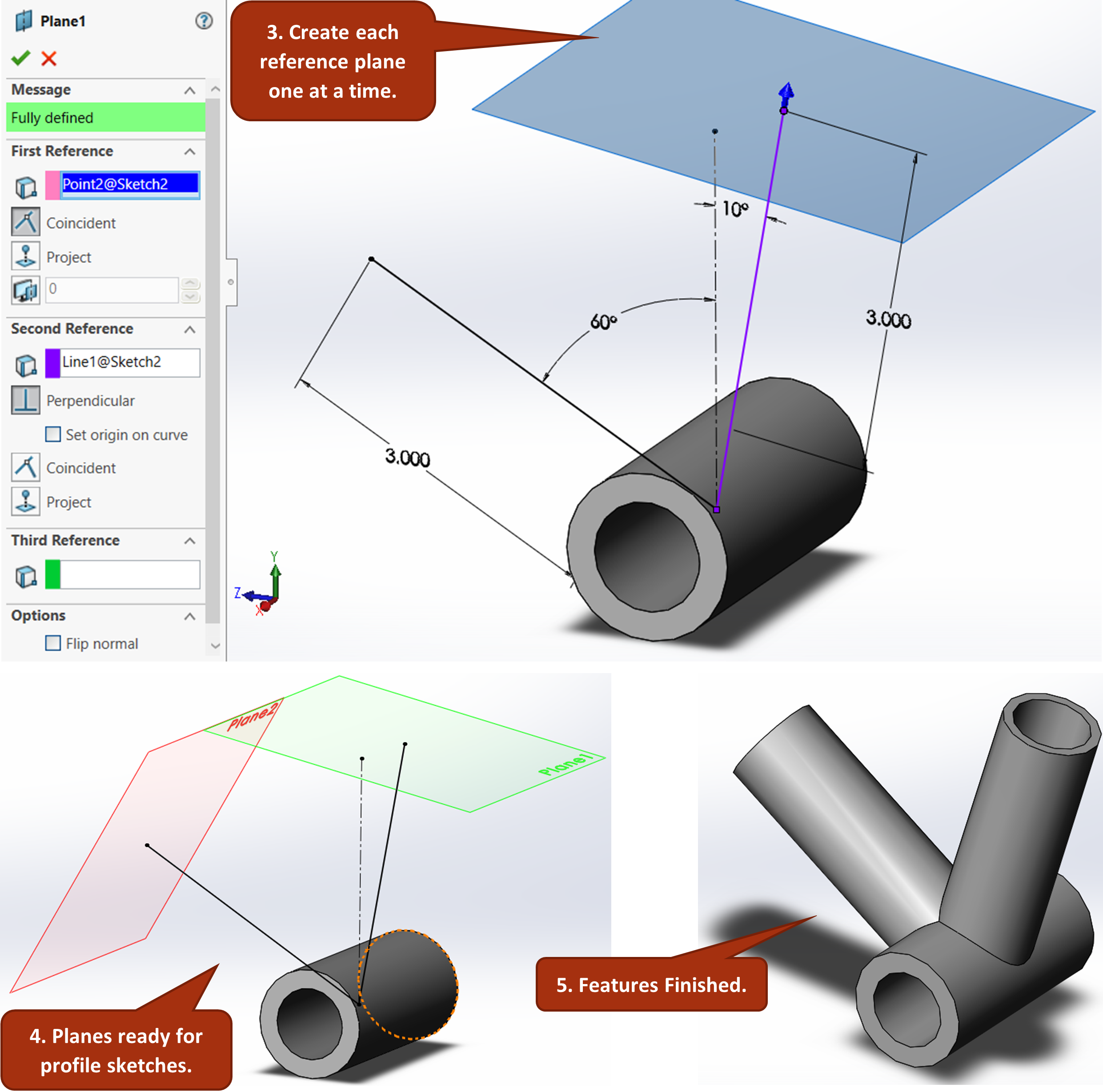
Reference Geometry Planes Introduction To Solidworks Part 1 Definition of a datum reference frame. this one starts out simple: a datum reference frame is a coordinate system, and preferably it is a cartesian coordinate system. coordinate systems are valuable because they’re used to locate objects. in gd&t they are used to orient and locate tolerance zones. datum reference frames and 6 degrees of freedom. In engineering and drafting, a datum is a reference point, surface, or axis on an object against which measurements are made. these are then referred to by one or more 'datum references' which indicate measurements that should be made with respect to the corresponding datum feature . in geometric dimensioning and tolerancing, datum reference. Gd&t flatness is a common symbol that references how flat a surface is regardless of any other datum’s or features. it comes in useful if a feature is to be defined on a drawing that needs to be uniformly flat without tightening any other dimensions on the drawing. the flatness tolerance references two parallel planes (parallel to the surface. Figure 2 an isometric drawing. any engineering drawing should show everything: a complete understanding of the object should be possible from the drawing. if the isometric drawing can show all details and all dimensions on one drawing, it is ideal. one can pack a great deal of information into an isometric drawing.

The Line Is Inclined To Both The Reference Plane Problem 1 Gd&t flatness is a common symbol that references how flat a surface is regardless of any other datum’s or features. it comes in useful if a feature is to be defined on a drawing that needs to be uniformly flat without tightening any other dimensions on the drawing. the flatness tolerance references two parallel planes (parallel to the surface. Figure 2 an isometric drawing. any engineering drawing should show everything: a complete understanding of the object should be possible from the drawing. if the isometric drawing can show all details and all dimensions on one drawing, it is ideal. one can pack a great deal of information into an isometric drawing. Definition of true position. the true position tolerance in gd&t informs us of the maximum allowable deviation of a feature (e.g. hole, slot) from its true position. by true position, we mean the ideal position of the feature according to design. the idea is that, for a feature, there is a true position that we desire. Geometric dimensioning and tolerancing (gd&t) is a system of symbols and standards used in engineering drawings and models to specify the required form, size, orientation, and location of parts and features. it is an important tool for ensuring the interchangeability, functional accuracy, and reliability of manufactured components.

Comments are closed.