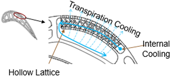
Diagram Of Lattice Cooling
Schematic Diagram Of The Integrated Cooling Model And Lattice Array Recent theories and experiments have suggested hydrodynamic phonon transport features in graphite at unusually high temperatures. here, we report a picosecond pump probe thermal reflectance measurement of heat pulse propagation in graphite. the measurement results reveal transient lattice cooling near the adiabatic center of a $15\\text{\\ensuremath{ }}\\ensuremath{\\mu}\\mathrm{m}$ diameter. As shown in fig. 6b, the lattice parameter change of the γ phase at a cooling rate of 1.0 × 10 3 °c s –1 was delayed without thermal shrinkage during cooling, that is, lattice expansion.

The Design Domains Of An Injection Mold With Lattice Cooling Sections The steel part of the phase diagram terefore has the typical lenticular two phase region during solidification. the start of solidification is described by the liquidus line and the end of solidification by the solidus line. the microstructure is formed between these lines with a correspondingly slower cooling rate. Lattice cooling by as much as 1 to 3 k was observed at 300 k by using a single or multiple barrier figure 1a illustrates the band diagram of the asymmetric double barrier heterostructure. a. Formation of ru 2 o orbital molecules on the pyrochlore lattice. (a) temperature dependent ru─o bond lengths (left) and ru─o─ru angles (right) obtained from the three identified crystal structures of in 2 ru 2 o 7. the bond lengths and bond angles relevant to the ru 2 o molecule are shown as squares and are enclosed in the gray region. Download scientific diagram | transient hydrodynamic heat backflow and lattice cooling. we show the vhe predictions for the relaxation in time of a temperature perturbation (obtained applying a.
Layout Of A Nf Cooling Lattice With Conventional Pb Cavities Field Formation of ru 2 o orbital molecules on the pyrochlore lattice. (a) temperature dependent ru─o bond lengths (left) and ru─o─ru angles (right) obtained from the three identified crystal structures of in 2 ru 2 o 7. the bond lengths and bond angles relevant to the ru 2 o molecule are shown as squares and are enclosed in the gray region. Download scientific diagram | transient hydrodynamic heat backflow and lattice cooling. we show the vhe predictions for the relaxation in time of a temperature perturbation (obtained applying a. The actual solidification process in steels takes place independently of the carbon content as in a solid solution alloy. this is shown in the phase diagram as a typical lenticular region between the liquidus and the solidus line. the carbon is completely soluble in the face centered cubic γ iron lattice structure immediately after solidification. Lattice cooling due to second sound propagation. (note: all the re ectance signals plotted in fig. 2, fig. 3 and fig. 4 are negative values. this is a more convenient way to illus trate the lattice cooling e ect because the dr dt coe cient is negative for graphite.) our measurement uses a picosecond laser of 1064 nm.

Integrated Transpiration And Lattice Cooling Systems Developed By The actual solidification process in steels takes place independently of the carbon content as in a solid solution alloy. this is shown in the phase diagram as a typical lenticular region between the liquidus and the solidus line. the carbon is completely soluble in the face centered cubic γ iron lattice structure immediately after solidification. Lattice cooling due to second sound propagation. (note: all the re ectance signals plotted in fig. 2, fig. 3 and fig. 4 are negative values. this is a more convenient way to illus trate the lattice cooling e ect because the dr dt coe cient is negative for graphite.) our measurement uses a picosecond laser of 1064 nm.

The Results In Stl Format A The Internal Lattice Cooling Structure

Comments are closed.