Digital Circuits Modelling In Simulink Let S Decode Part 7

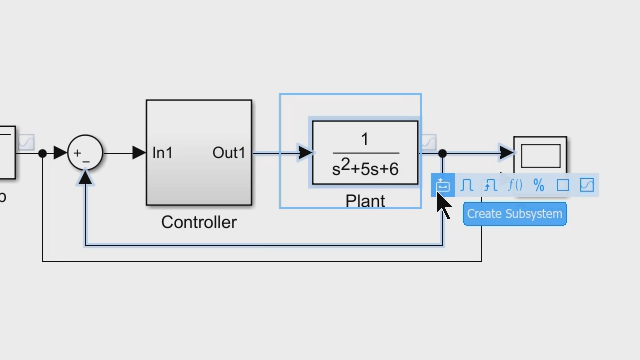
Digital Circuits Modelling In Simulink Let S Decode Part 7 Simulink, an add on product to matlab, provides an interactive, graphical, environment for modelling, simulating, and analyzing of dynamic systems. in this s. Simulink, an add on product to matlab, provides an interactive, graphical, environment for modelling, simulating, and analyzing of dynamic systems. i this vi.
Simulating Electronic Circuits Using Simulink Robocraze A noninverting op amp circuit. the gain is given by 1 r2 r1, and with the values set to r1=1k ohm and r2=10k ohm, the 0.1v peak to peak input voltage is amplified to 1.1v peak to peak. as the op amp block implements an ideal (i.e. infinite gain) device, this gain is achieved regardless of output load. Open a new blank model to contain your first circuit and save it as circuit1. add the ac voltage source block from the simscape > electrical > specialized power systems > sources library. set the amplitude, phase, and frequency parameters of the ac voltage source block according to the values shown in circuit to be modeled. Double clicking on the block allows us to set the pin to 0 from the drop down menu. we also will set the sample time to "0.1". this is 10 times faster than the circuit's time constant and hence is sufficiently fast. the other blocks in the model can also be set to have a sample time of "0.1" (or left as " 1"). In this article, we use model based design with matlab and simulink to design a sigma delta analog to digital converter (adc). beginning with a high level behavioral model of the adc, we elaborate the design and finally, generate synthesizable vhdl code. the files for this design are available for download.

Adding Components To Your Simulink Model Getting Started With Double clicking on the block allows us to set the pin to 0 from the drop down menu. we also will set the sample time to "0.1". this is 10 times faster than the circuit's time constant and hence is sufficiently fast. the other blocks in the model can also be set to have a sample time of "0.1" (or left as " 1"). In this article, we use model based design with matlab and simulink to design a sigma delta analog to digital converter (adc). beginning with a high level behavioral model of the adc, we elaborate the design and finally, generate synthesizable vhdl code. the files for this design are available for download. Matlab and simulink enable you to model analog circuits, digital controllers, fsms, and dsp elements together, facilitating early what if analysis and verification. you can reuse these models in eda flows, promoting a shift left approach. products like mixed signal blockset let you explore the design space and perform static analysis of plls. Ons and hand off production ready algorithmic code to your software engineersthese are among the 10 proven ways to use system level simulation with s. mu. ink to improve your design process for digital control. or power converters.1. simulate analog and digital components at the same timebefore you can use simulations in the design of a digital.

Comments are closed.