Dimensions In Engineering Drawing Explained Iso

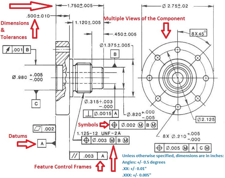
Dimensions In Engineering Drawing Explained Iso Youtube In this video, we are going to learn about dimensions in engineering drawing! we are going to look at what dimensioning is, what are the elements of the dime. As basic dimensions are perfect, there would be no deviations, and they would not be recorded on the report. instead of basic dimensions, we would report the following: flatness for datum a. size of the part (60 0.1 for length and width) thickness of the part (16 0.1) size of the holes (Ø12 0.05) position of the holes (cylindrical.

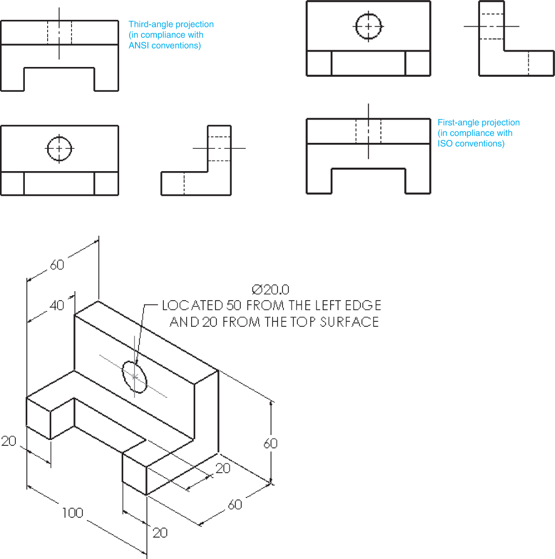
Types Of Dimensions In Engineering Drawing At Getdrawings Free Download Engineering drawing basics explained. an engineering drawing is a subcategory of technical drawings. the purpose is to convey all the information necessary for manufacturing a product or a part. engineering drawings use standardised language and symbols. this makes understanding the drawings simple with little to no personal interpretation. Figure 2 an isometric drawing. any engineering drawing should show everything: a complete understanding of the object should be possible from the drawing. if the isometric drawing can show all details and all dimensions on one drawing, it is ideal. one can pack a great deal of information into an isometric drawing. Diameters must be dimensioned with the diameter symbol preceding the numerical value. when holes are dimensioned with a leader line, the line must be radial. a radial line is one that passes through the center of a circle or arc if extended. symbols may be used for spotface, counterbore, and countersunk holes. Iso 1101:1983 ext 1:1983. technical drawings — geometrical tolerancing — tolerancing of form, orientation, location and run out — generalities, definitions, symbols, indications on drawings — extract 1: toleranced characteristics and symbols — examples of indication and interpretation. 95.99.

Isometric Drawing With Dimensions Diameters must be dimensioned with the diameter symbol preceding the numerical value. when holes are dimensioned with a leader line, the line must be radial. a radial line is one that passes through the center of a circle or arc if extended. symbols may be used for spotface, counterbore, and countersunk holes. Iso 1101:1983 ext 1:1983. technical drawings — geometrical tolerancing — tolerancing of form, orientation, location and run out — generalities, definitions, symbols, indications on drawings — extract 1: toleranced characteristics and symbols — examples of indication and interpretation. 95.99. 1. basic requirements for dimensioning of assembly. 1. the dimensions shall be complete, and the shape and size of the object shall be completely determined without omission or repetition. 2. the dimensions shall comply with the provisions of national standards, that is, strictly abide by national standards. 3. Iso 3040:1990, technical drawings — dimensioning and tolerancing — cones [7] iso 3898:1997, bases for design of structures — notations — general symbols [8] iso 5457:1999, technical product documentation — sizes and layout of drawings sheets [9] iso 6433:1981, technical drawings — item references [10].

Isometric Drawings With Dimensions 1. basic requirements for dimensioning of assembly. 1. the dimensions shall be complete, and the shape and size of the object shall be completely determined without omission or repetition. 2. the dimensions shall comply with the provisions of national standards, that is, strictly abide by national standards. 3. Iso 3040:1990, technical drawings — dimensioning and tolerancing — cones [7] iso 3898:1997, bases for design of structures — notations — general symbols [8] iso 5457:1999, technical product documentation — sizes and layout of drawings sheets [9] iso 6433:1981, technical drawings — item references [10].

Dimensions In Engineering Drawing Youtube

Comments are closed.