Electrical Wiring Diagram Of Heating And Cooling System

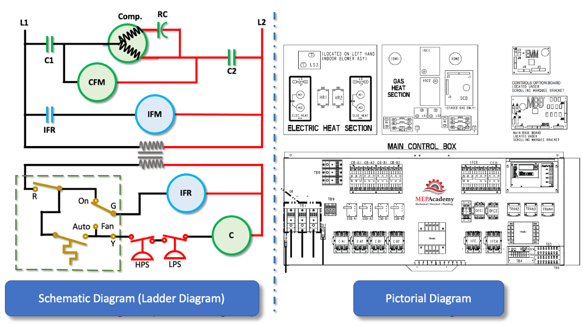
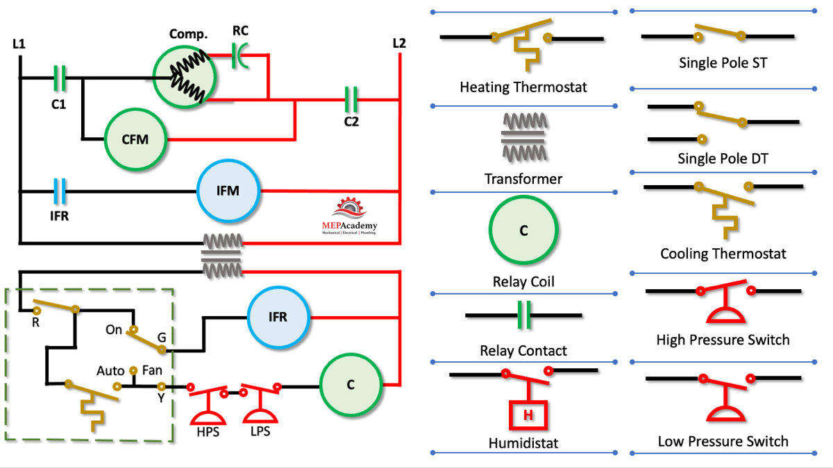
How To Read Wiring Diagrams In Hvac Systems Mep Academy These control the power, heat and fan. standard thermostats use 4 or 5 wires: r, w, g, y, and sometimes c. these control the power, heat, fan, and cooling. more advanced thermostats use 6 8 wires. the extra wires control additional hvac system features and settings, signaling a two stage cooling or heat pump system. An hvac wiring diagram is a visual representation of the electrical components and their connections in a heating, ventilation, and air conditioning system. it is an essential tool for understanding and troubleshooting the electrical system of an hvac system. the diagram illustrates the flow of electrical current and provides a detailed.

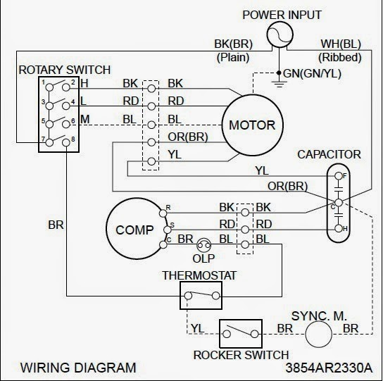
How To Install Electric Heating System At William Paulsen Blog In the hvac (heating, ventilation, and air conditioning) industry, understanding wiring diagrams is crucial for technicians and installers. these diagrams provide a visual representation of the electrical connections and components involved in an hvac system, allowing professionals to troubleshoot and repair any issues effectively. Understanding hvac wiring diagrams is essential for professionals working in the heating, ventilation, and air conditioning industry. these diagrams are like blueprints that offer a visual representation of the electrical wiring in hvac systems. it’s crucial to comprehend these diagrams to troubleshoot, repair, and install hvac equipment. It is an essential component in thermostat wiring and is commonly used in heat pump systems for heating. additionally, a wiring diagram can be helpful when installing or troubleshooting these systems. it is usually a thicker gauge wire capable of handling higher voltage levels, especially when it comes to thermostat wiring and heating. The hvac wiring diagram thermostat illustrates the electrical connections between the thermostat, the heating or cooling system, and the power supply. it shows the different wires and terminals involved in the system and their corresponding functions. the diagram provides a visual representation of how the thermostat interacts with the hvac.

Electrical Wiring Diagrams For Air Conditioning Systems Part Two It is an essential component in thermostat wiring and is commonly used in heat pump systems for heating. additionally, a wiring diagram can be helpful when installing or troubleshooting these systems. it is usually a thicker gauge wire capable of handling higher voltage levels, especially when it comes to thermostat wiring and heating. The hvac wiring diagram thermostat illustrates the electrical connections between the thermostat, the heating or cooling system, and the power supply. it shows the different wires and terminals involved in the system and their corresponding functions. the diagram provides a visual representation of how the thermostat interacts with the hvac. A new system may need as many as ten wires (like a two stage heat, two stage cooling system, heat pump reversing valves, fan control, etc.) if the system had two stage heating, and or cooling, the 2nd stage termainals would be labelled w1 and w2 for heating, y1 and y2 for cooling. these additional terminals are not shown in this diagram. In hvac wiring diagrams, the symbol for the power supply represents the electrical source that provides the necessary energy to operate the heating, ventilation, and air conditioning system. this symbol typically consists of a straight line with a small circle at the end, indicating the connection point to the power source.

How To Read Wiring Diagrams In Hvac Systems Mep Academy A new system may need as many as ten wires (like a two stage heat, two stage cooling system, heat pump reversing valves, fan control, etc.) if the system had two stage heating, and or cooling, the 2nd stage termainals would be labelled w1 and w2 for heating, y1 and y2 for cooling. these additional terminals are not shown in this diagram. In hvac wiring diagrams, the symbol for the power supply represents the electrical source that provides the necessary energy to operate the heating, ventilation, and air conditioning system. this symbol typically consists of a straight line with a small circle at the end, indicating the connection point to the power source.

Hvac Wiring Explained

Wiring Diagram For Y Plan Central Heating System Easy Wiring

Comments are closed.