Engineering Drawing Layout Of Drawing Sheets

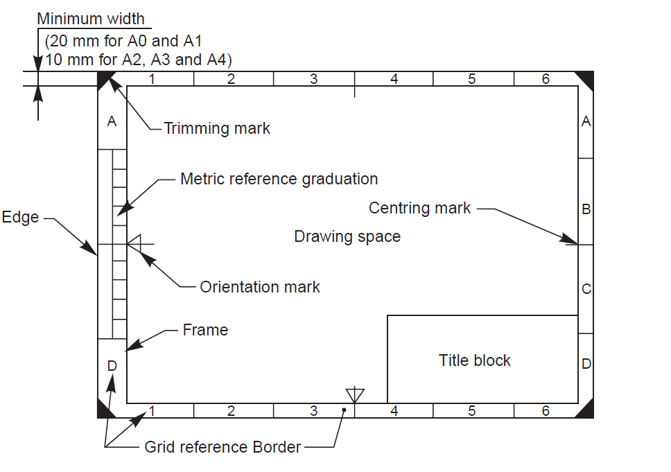
Engineering Drawing Layout Of Drawing Sheets Engineering working drawings basics page 2 of 22 drawing sheet layout standard layouts of drawing sheets are specified by the various standards organizations. the figure shows the layout of a typical sheet, showing the drawing frame, a typical title block, parts list (bill of materials) and revision table. First, we will consider the sheet sizes, drawing format, title blocks, and other parameters of the drawing form. standard sheet sizes in table 1 are shown the most widely used a and b series of the iso drawing sheet sizes, with a4 being the most popular size. the terms used in the table are clarified here: the inside border encloses the working area, including the title block and other tables.

Engineering Drawing Basic Sheet Layout Title Block Notes An engineering (or technical) drawing is a graphical representation of a part, assembly, system, or structure and it can be produced using freehand, mechanical tools, or computer methods. working drawings are the set of technical drawings used during the manufacturing phase of a product. they contain all the information needed to manufacture. To prepare a drawing, one can use manual drafting instruments (figure 12) or computer aided drafting or design, or cad. the basic drawing standards and conventions are the same regardless of what design tool you use to make the drawings. in learning drafting, we will approach it from the perspective of manual drafting. Drawing tools 2d and 3d engineering drawing tools. miscellaneous engineering related topics like beaufort wind scale, ce marking, drawing standards and more. related documents drawing scales commonly used blueprint drawing scales. lengths and areas vs. mapping scales convert lengths areas between different mapping scales. 9 eraser. per session. 10 sand paper cello tape. 11 blade pencil sharpener. 12 drawing sheet. students without engineering drawing box will not be allowed to attend the practical session. school instrument box is not allowed. 10. mini drafter fixed on a drawing table 12. drawing clips french curves.

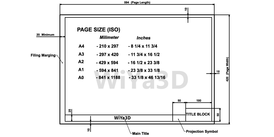
Introduction Of Sheets And Sheet Layout Engineering Drawing By Engg Drawing tools 2d and 3d engineering drawing tools. miscellaneous engineering related topics like beaufort wind scale, ce marking, drawing standards and more. related documents drawing scales commonly used blueprint drawing scales. lengths and areas vs. mapping scales convert lengths areas between different mapping scales. 9 eraser. per session. 10 sand paper cello tape. 11 blade pencil sharpener. 12 drawing sheet. students without engineering drawing box will not be allowed to attend the practical session. school instrument box is not allowed. 10. mini drafter fixed on a drawing table 12. drawing clips french curves. A drawing file contains one or more drawing sheets on which 2 dimensional and or 3 dimensional scaled views of the solid models contained in part, assembly, or presentation files. a drawing file has the file extension .idw. idw is an acronym for inventor drawing. annotations can be automatically or manually added to the views as required. All drawings require a boarder. the standard line thickness of the boarder is 0.6 mm. the top, right and bottom margin should be 10 mm and the left margin should be 20 mm. this applies for all sheet sizes (a0, a1, a2, a3, a4). notice that the left marigns in larger to allow space for binding a drawing set boarder lineweight: 0.60 mm.

Engineering Drawing And Best Practice Wiya3d A drawing file contains one or more drawing sheets on which 2 dimensional and or 3 dimensional scaled views of the solid models contained in part, assembly, or presentation files. a drawing file has the file extension .idw. idw is an acronym for inventor drawing. annotations can be automatically or manually added to the views as required. All drawings require a boarder. the standard line thickness of the boarder is 0.6 mm. the top, right and bottom margin should be 10 mm and the left margin should be 20 mm. this applies for all sheet sizes (a0, a1, a2, a3, a4). notice that the left marigns in larger to allow space for binding a drawing set boarder lineweight: 0.60 mm.

Comments are closed.