Engineering Drawing Reference Dimension вђ Otosection

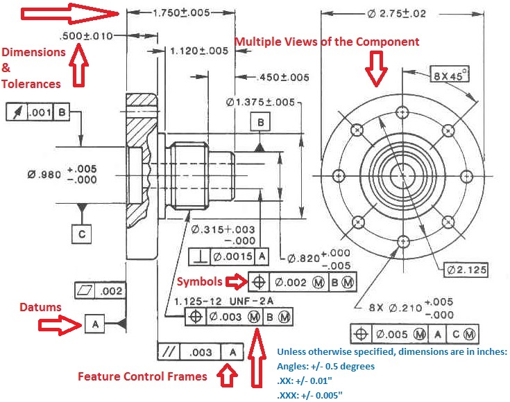
Types Of Dimensions In Engineering Drawing At Getdrawings Free Download A reference dimension is just what it sounds like. it is a dimension shown for reference. in other words it is there for informational purposes only. they are not a requirement in any way. reference dimensions can be used to clarify other dimensions on a drawing. in some instances, they make a drawing easier to understand. Reference dimensions. reference dimensions are supplementary measurements provided on an engineering drawing to clarify the size or location of features, but they are not intended to control manufacturing or inspection processes. these dimensions are enclosed in parentheses and serve only as informational aids, often derived from other basic.

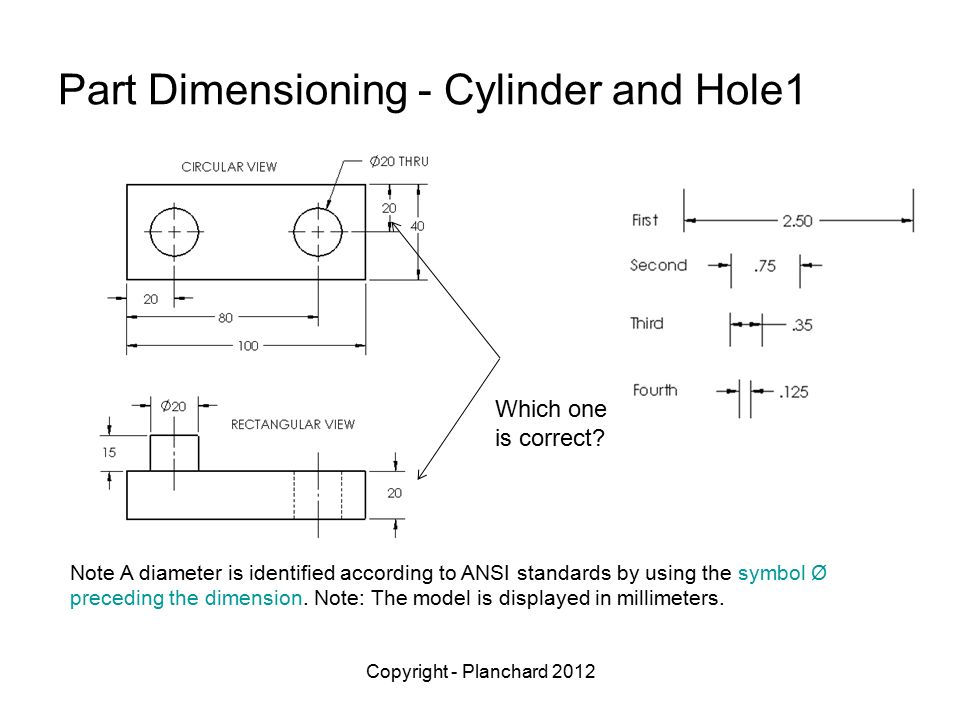
Types Of Dimensions In Engineering Drawing At Getdrawings Free Download A half section is a view of an object showing one half of the view in section, as in figure 19 and 20. figure 19 full and sectioned isometric views. figure 20 front view and half section. the diagonal lines on the section drawing are used to indicate the area that has been theoretically cut. these lines are called section lining or cross. Powerpoint presentation. asme y14.35m; “revision of engineering drawings and associated documents”. this standard defines the practices of revising drawings and associated documentation and establishes methods for identification and recording revisions. the revision practices of this standard apply to any form of original drawing and. The cross section view shown in figure 2 can help clarify this; without the centerlines, the ‘holes’ would be considered rectangular in this part rather than circular. centerlines are used as a reference to dimension circular features. whenever you want to dimension a circular feature, it is best to use its mid point as a reference. Use appropriate units: choose the appropriate units of measurement for the drawing. in most cases, millimeters are the preferred unit for engineering drawings. however, inches or other units may be used in certain situations. apply tolerances: tolerances specify the allowable variation in a dimension.

Dimension Drawing Symbols The cross section view shown in figure 2 can help clarify this; without the centerlines, the ‘holes’ would be considered rectangular in this part rather than circular. centerlines are used as a reference to dimension circular features. whenever you want to dimension a circular feature, it is best to use its mid point as a reference. Use appropriate units: choose the appropriate units of measurement for the drawing. in most cases, millimeters are the preferred unit for engineering drawings. however, inches or other units may be used in certain situations. apply tolerances: tolerances specify the allowable variation in a dimension. Units of measurement. the units of the print are very important because there is a huge difference between 25.4mm and 25.4 inches. the measurement units will often be called out in the title block or tolerance block but occasionally will be in another section of the blueprint such as in the notes. angular units are important also but there is. 1. basic requirements for dimensioning of assembly. 1. the dimensions shall be complete, and the shape and size of the object shall be completely determined without omission or repetition. 2. the dimensions shall comply with the provisions of national standards, that is, strictly abide by national standards. 3.

Comments are closed.