How Can I Use Reference Dimension To Drive A Sketch Dimension In The
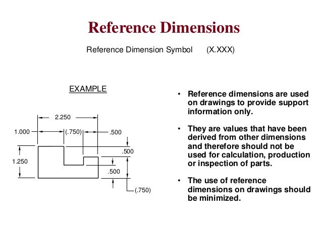
How Can I Use Reference Dimension To Drive A Sketch Dimension In The To add a reference dimension: click smart dimension (dimensions relations toolbar) or click tools > dimensions > smart. in a drawing view, click the items you want to dimension. you can dimension to a silhouette edge. point to the silhouette edge, and when the pointer appears, click to dimension. use rapid dimensioning to place evenly spaced. A reference dimension is just what it sounds like. it is a dimension shown for reference. in other words it is there for informational purposes only. they are not a requirement in any way. reference dimensions can be used to clarify other dimensions on a drawing. in some instances, they make a drawing easier to understand.
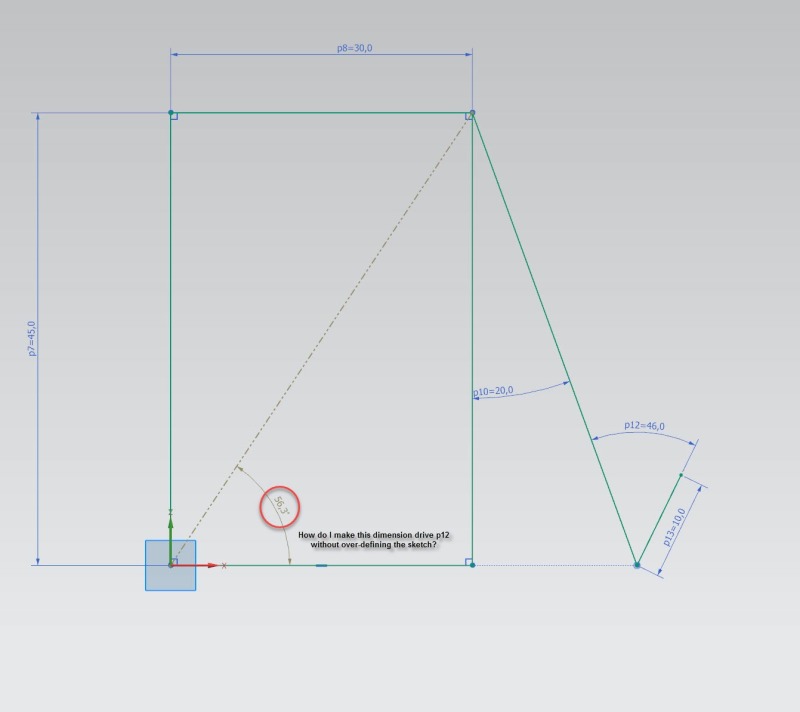
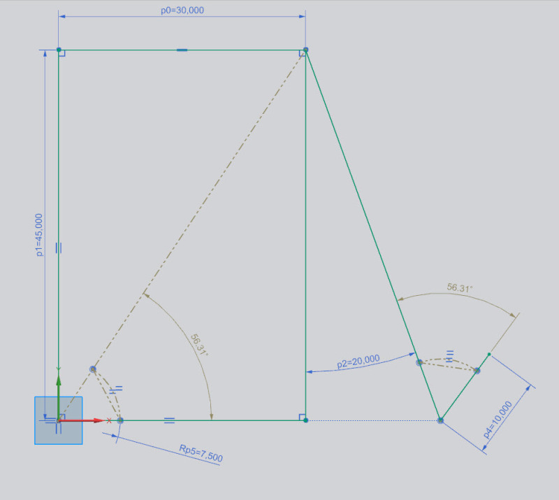
How Can I Use Reference Dimension To Drive A Sketch Dimension In The You can insert driven (reference) dimensions when creating sketch entities. this is helpful if you want to switch between inserting driving and driven dimensions. this functionality is available for lines, rectangles, circles, and arcs. click a sketch tool. in the graphics area, right click and click sketch numeric input . It seems that as soon as i make a driving dimension a reference dimension, i lose the ability to use that value in an expression. i've attach an example sketch describing what i mean. being new to nx and coming from a solidworks background, i'm used to being able to do this and it really helps with visualizing how geometry changes with a given. I think the problem is that section relations (that is, the ones that have the sd0 "sketch dimensions") can only reference part parameters: however, you can make a sketch feature relation that can drive the generated "feature dimension" to be equal to the value of other parameters in the model, including its own sketch feature parameters (in which case, the :fid xxxxx syntax is unnecessary):. I have another body in that document in which a sketch uses that driven dimension from the first sketch to drive a dimension in the second sketch. i therefore gave the first dimension a name, and clicked the "reference" checkbox, thinking that would let me reference the dimension in the new sketch in another body, using some sort of path.
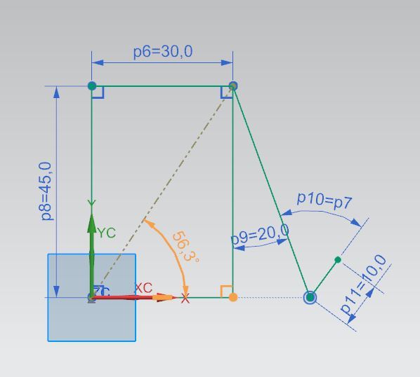
How Can I Use Reference Dimension To Drive A Sketch Dimension In The I think the problem is that section relations (that is, the ones that have the sd0 "sketch dimensions") can only reference part parameters: however, you can make a sketch feature relation that can drive the generated "feature dimension" to be equal to the value of other parameters in the model, including its own sketch feature parameters (in which case, the :fid xxxxx syntax is unnecessary):. I have another body in that document in which a sketch uses that driven dimension from the first sketch to drive a dimension in the second sketch. i therefore gave the first dimension a name, and clicked the "reference" checkbox, thinking that would let me reference the dimension in the new sketch in another body, using some sort of path. Oct 10, 2007. 41. us. hello everyone, i am having an issue that just started somehow and am looking for some help to resolve. i am running st2 and created a sheet metal part. i then tried to add a cut to the part and i am having issues dimensioning the sketch. anytime i add a new dimension to the sketch it comes in as reference blue. In drawings, they are reference dimensions and you cannot change their values or use the values to drive the model. angular running dimensions. angular running dimensions are a set of dimensions measured from a zero degree dimension in a drawing or sketch. chamfer dimensions. you can dimension chamfers in drawings.
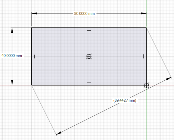
Dimension Oct 10, 2007. 41. us. hello everyone, i am having an issue that just started somehow and am looking for some help to resolve. i am running st2 and created a sheet metal part. i then tried to add a cut to the part and i am having issues dimensioning the sketch. anytime i add a new dimension to the sketch it comes in as reference blue. In drawings, they are reference dimensions and you cannot change their values or use the values to drive the model. angular running dimensions. angular running dimensions are a set of dimensions measured from a zero degree dimension in a drawing or sketch. chamfer dimensions. you can dimension chamfers in drawings.
Engineering Drawing Notes B

Comments are closed.