How To Display Reference Part Same As Normal Part In Inventor Drawing

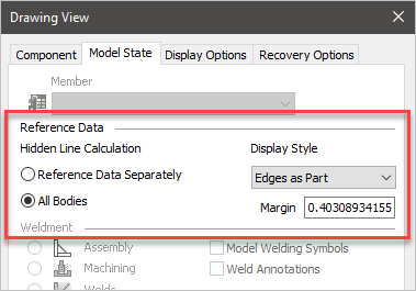
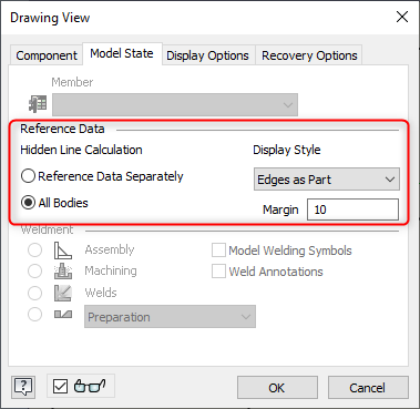
How To Display Reference Part Same As Normal Part In Inventor Drawing Solution: use one of the following: in bom structure column in assembly environment, select phantom, instead of reference. in drawing view dialog box, select 'hidden line calculation: all bodies', and 'display style: edges as part'. the reference part will be shown as default part. Have a simple assembly that has 3 parts all in the relatively same plane, make the outside ones reference (under iproperties in the assembly context). create a base view of that assembly (adjusting the view margin so that you can see the outside reference parts. even if you say "as parts" under line style in the view dialog, we don't crosshatch.

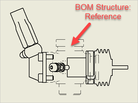
How To Display Reference Part Same As Normal Part In Inventor Drawing Rmb on the part in your main assembly and make sure bom reference is not set. to reference. you can (for any component) override its document level bom. structure attribute to be reference. . andrew faix. product designer inventor drawing manager. autodesk. "gary cross ( iv10 sp1)" wrote in message. This will turn the part to a reference part in all assembly by default. if you only want the part to be reference in one assembly, not in others, you should not change the option in document settings. instead, you should leave the doc settings > bom for the part as normal. so, the part's default bom structure would be normal (counted in bom). Within drawings, they appear by default with a double dashed chain line and the drawing view may not fully include them: if needed to have reference components shown as normal, the following settings can be adjusted (right click a view > edit view > model state): display style line style (for inventor 2020 and older): edges as part as parts. Select the associative check box to update the drawing when changes are made to the associative design view representation in the part or assembly environment. click the view settings icon to set the view representation preferences for the base view. available for base view creation only.

How To Display Reference Part Same As Normal Part In Inventor Drawing Within drawings, they appear by default with a double dashed chain line and the drawing view may not fully include them: if needed to have reference components shown as normal, the following settings can be adjusted (right click a view > edit view > model state): display style line style (for inventor 2020 and older): edges as part as parts. Select the associative check box to update the drawing when changes are made to the associative design view representation in the part or assembly environment. click the view settings icon to set the view representation preferences for the base view. available for base view creation only. Right click the view and select edit view. in the drawing view dialog box, select the model state tab. under reference data, select the desired line type you want the reference part to have. if you set it to off, all reference parts will not be visible in your drawing view. if you set it to as parts, the reference parts will appear as if they. Mechanical. the hidden lines are because the part is reference, and turning them back to normal will fix the problem. however, you can keep the parts as ref and keep your bom straight or to keep your weight and cog correct (ref parts are weightless unless made flexible). click on the view in the idw and pick edit view and go to the options tab.

Inventor Reference Components In Drawings Cadline Community Right click the view and select edit view. in the drawing view dialog box, select the model state tab. under reference data, select the desired line type you want the reference part to have. if you set it to off, all reference parts will not be visible in your drawing view. if you set it to as parts, the reference parts will appear as if they. Mechanical. the hidden lines are because the part is reference, and turning them back to normal will fix the problem. however, you can keep the parts as ref and keep your bom straight or to keep your weight and cog correct (ref parts are weightless unless made flexible). click on the view in the idw and pick edit view and go to the options tab.

Inventor Create A Drawing And Parts List Youtube

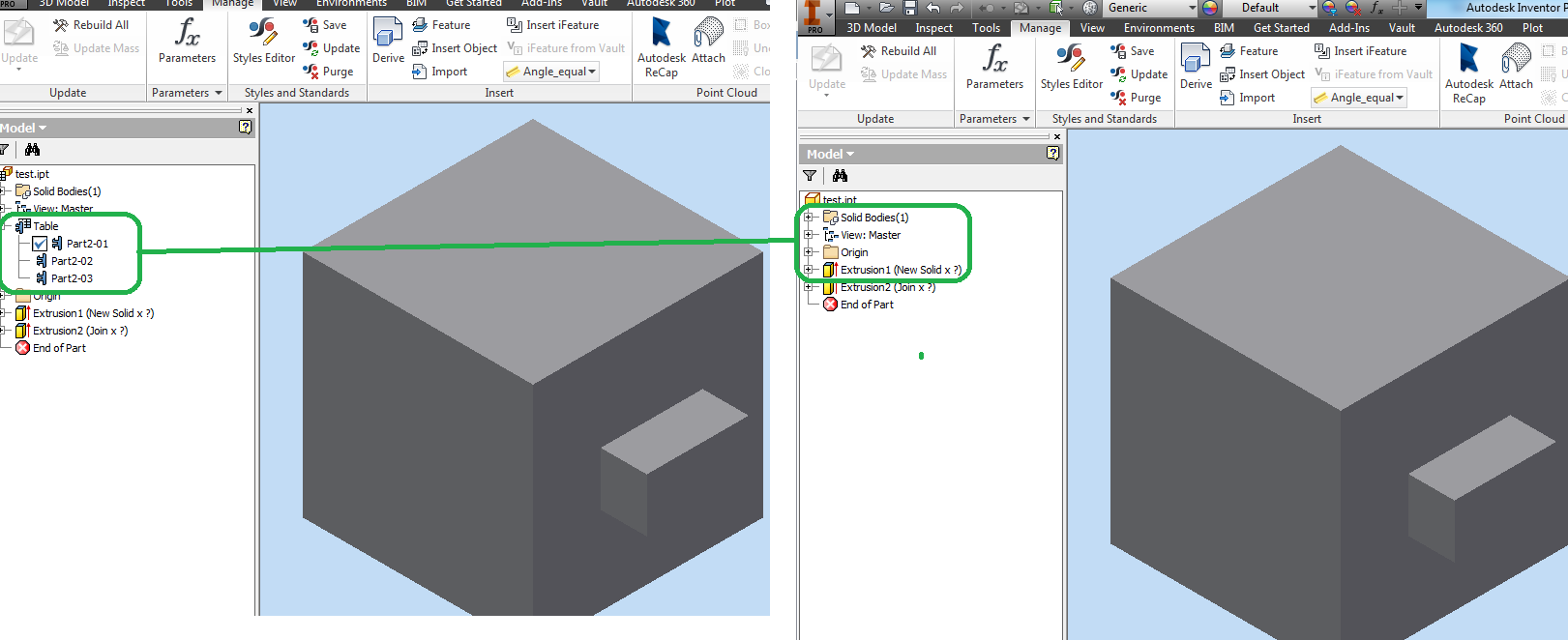
How To Convert An Ipart Or Iassembly In Normal Part Or Assembly In Inventor

Comments are closed.