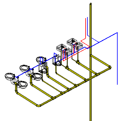
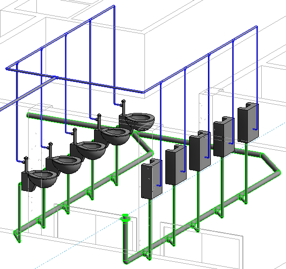
How To Draw Piping Systems In Revit Drag And Draw Fittings Added

How To Draw Piping Systems In Revit Drag And Draw Fittings Added Download a free trial of the mepcontent product line placer for piping here: store.mepcontent en product details 7or visit the full page of the a. When you draw a pipe, it uses a pipe series family that defines pipe sizes to use and what fittings to use by default. there seems to be connectors in your family (only looked at the screenshot), do they use preset connection size? if so, i think that pipe series needs to have those size defined also.

Piping Design Work In Revit Youtube You should be able to call out the stacked pipes on the plan, size and system, and refer to a section or elevation view to see the vertical orientation. since you are being directed to do show them all on plan, i would draw annotation lines or pipe place holders to cheat the view into displaying three lines. rob. To create a new piping system type for this example, in the project browser, scroll down and expand piping systems > piping system. right click hydronic supply and select type properties. in the type properties dialog, click duplicate. in the name dialog, enter “heating hot water supply”, and then click ok. On the end of the open pipe, right click the node and select draw pipe specify an elevation and draw the pipe. you cannot be in a straight on 3d view, it has to be tilted a little bit in any direction. please click accept as solution if this answers your question! report. You can design piping systems for a variety of applications, such as hydronic heating and oxygen distribution systems. add equipment. place mechanical equipment in spaces according to the piping component schedule. you can create groups of components to replicate similar systems in other spaces or on other levels. create piping systems.

Piping Systems Revit 2022 Autodesk Knowledge Network On the end of the open pipe, right click the node and select draw pipe specify an elevation and draw the pipe. you cannot be in a straight on 3d view, it has to be tilted a little bit in any direction. please click accept as solution if this answers your question! report. You can design piping systems for a variety of applications, such as hydronic heating and oxygen distribution systems. add equipment. place mechanical equipment in spaces according to the piping component schedule. you can create groups of components to replicate similar systems in other spaces or on other levels. create piping systems. Creating piping systems. plumbing systems are logical entities that facilitate calculations for flow and sizing of equipment. they are independent of the piping that is placed in a project to show the routing and connections between plumbing fixtures. once you have fixtures placed in a project, you can create domestic hot water, domestic cold. Modeling using sysque systems pipe to draw a line of pipe using the selected system, click on the button for straight pipe in the sysque® systems pipe system window. across the top of the modeling area appears a new properties bar. of particular interest are two items, the diameter textboxes (b) and the offset combo box (c). 1.

Piping System In Revit Youtube Creating piping systems. plumbing systems are logical entities that facilitate calculations for flow and sizing of equipment. they are independent of the piping that is placed in a project to show the routing and connections between plumbing fixtures. once you have fixtures placed in a project, you can create domestic hot water, domestic cold. Modeling using sysque systems pipe to draw a line of pipe using the selected system, click on the button for straight pipe in the sysque® systems pipe system window. across the top of the modeling area appears a new properties bar. of particular interest are two items, the diameter textboxes (b) and the offset combo box (c). 1.

How To Draw Drainage Pipework In Revit 7 Tips Youtube

Revit Mep Tutorial Creating Drain Route Cadnotes

Comments are closed.