How To Reference The Grid On A Technical Drawing

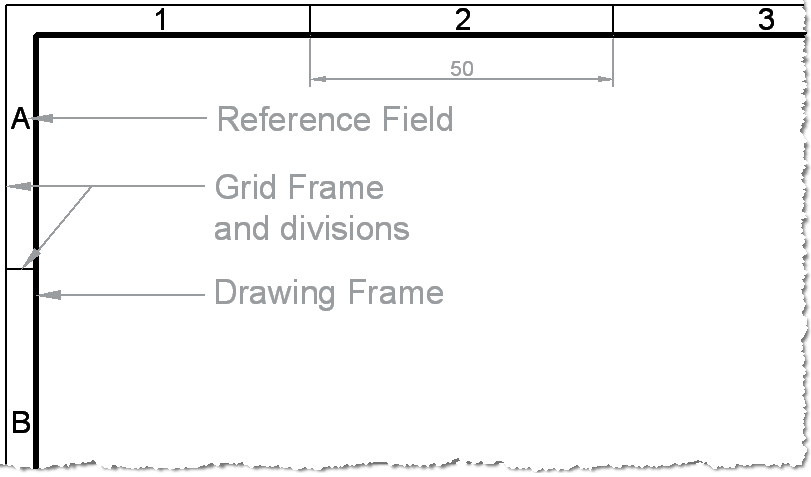
Technical Drawing Standards Grid Reference Frame Grid references. the grid references start from the top left of the sheet, with letters running vertically from the top down and numbers running horizontally from left to right. on an a4 sheet the grids only need to be drawn on the top and left hand side. the letters i and o are not used – because they could be confused with 1 and 0. Reference markers are labels on a drawing that indicated where the drawing is taken from and what it is showing. these consist of elevation markers, section markers and detail markers. for example, you will use your floor plan to show the reader the points at which you will take an elevation, or a section line through the building.

Grid Reference On Structural Drawings Youtube In order for structural drawings to fit on a manageable sized drawing sheet, the drawing is usually a small fraction of the real world size. a scale of 1:100 is a very common scale to use for a structural framing plan. that is, a 1mm measurement taken on the drawing represents a 100mm length of the real world object. Engineering working drawings basics. engineering graphics is an effective way of communicating technical ideas and it is an essential tool in engineering design where most of the design process is graphically based. engineering graphics is used in the design process for visualization, communication, and documentation. In a standard set of architectural plans on a small residential project, the elevations will most likely be a set of drawings from the main facades of the building. for example, front, back and two sides – or north, south, east and west. the sections would most likely be two or more sections cut at 90 degrees of one another to give. To help locate a specific point on a referenced print, most drawings, especially piping and instrument drawings (p&id) and electrical schematic drawings, have a grid system. the grid can consist of letters, numbers, or both that run horizontally and vertically around the drawing as illustrated below. like a city map, the drawing is divided into.

How To Draw Using A Grid Grid Drawing Tutorial Youtube In a standard set of architectural plans on a small residential project, the elevations will most likely be a set of drawings from the main facades of the building. for example, front, back and two sides – or north, south, east and west. the sections would most likely be two or more sections cut at 90 degrees of one another to give. To help locate a specific point on a referenced print, most drawings, especially piping and instrument drawings (p&id) and electrical schematic drawings, have a grid system. the grid can consist of letters, numbers, or both that run horizontally and vertically around the drawing as illustrated below. like a city map, the drawing is divided into. An engineering drawing provides details such as first angle projections, hidden lines, extension lines, etc., which are crucial for precise manufacturing. they include cross sectional views or an auxiliary view that reveal hidden features and internal details, which a 3d model alone cannot fully convey. while 3d models are valuable for visual. 6. ensure views align with the projection view. once you start drawing, it is important to use the correct projection alignment. the person fabricating the part will use this orientation during manufacturing, so make sure that all the views follow the alignment convention that is specified in the title block.

Reference Points Grid Drawing Practice Youtube An engineering drawing provides details such as first angle projections, hidden lines, extension lines, etc., which are crucial for precise manufacturing. they include cross sectional views or an auxiliary view that reveal hidden features and internal details, which a 3d model alone cannot fully convey. while 3d models are valuable for visual. 6. ensure views align with the projection view. once you start drawing, it is important to use the correct projection alignment. the person fabricating the part will use this orientation during manufacturing, so make sure that all the views follow the alignment convention that is specified in the title block.

How To Draw Using The Grid Method Drawing Grid Drawings Drawing

How To Draw Using A Reference And Grid Youtube

Comments are closed.