Ignition Wiring Diagram Johnson Outboard

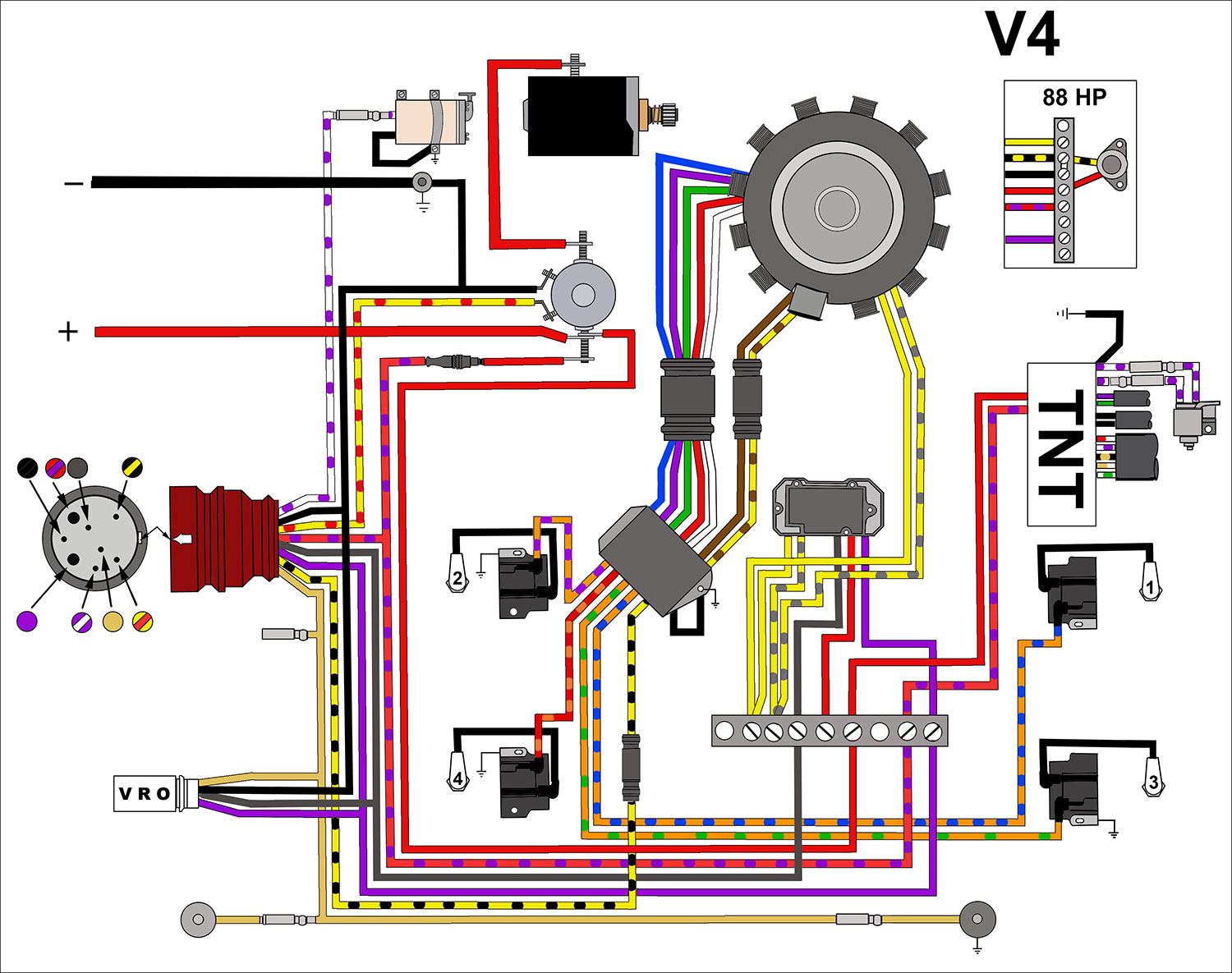
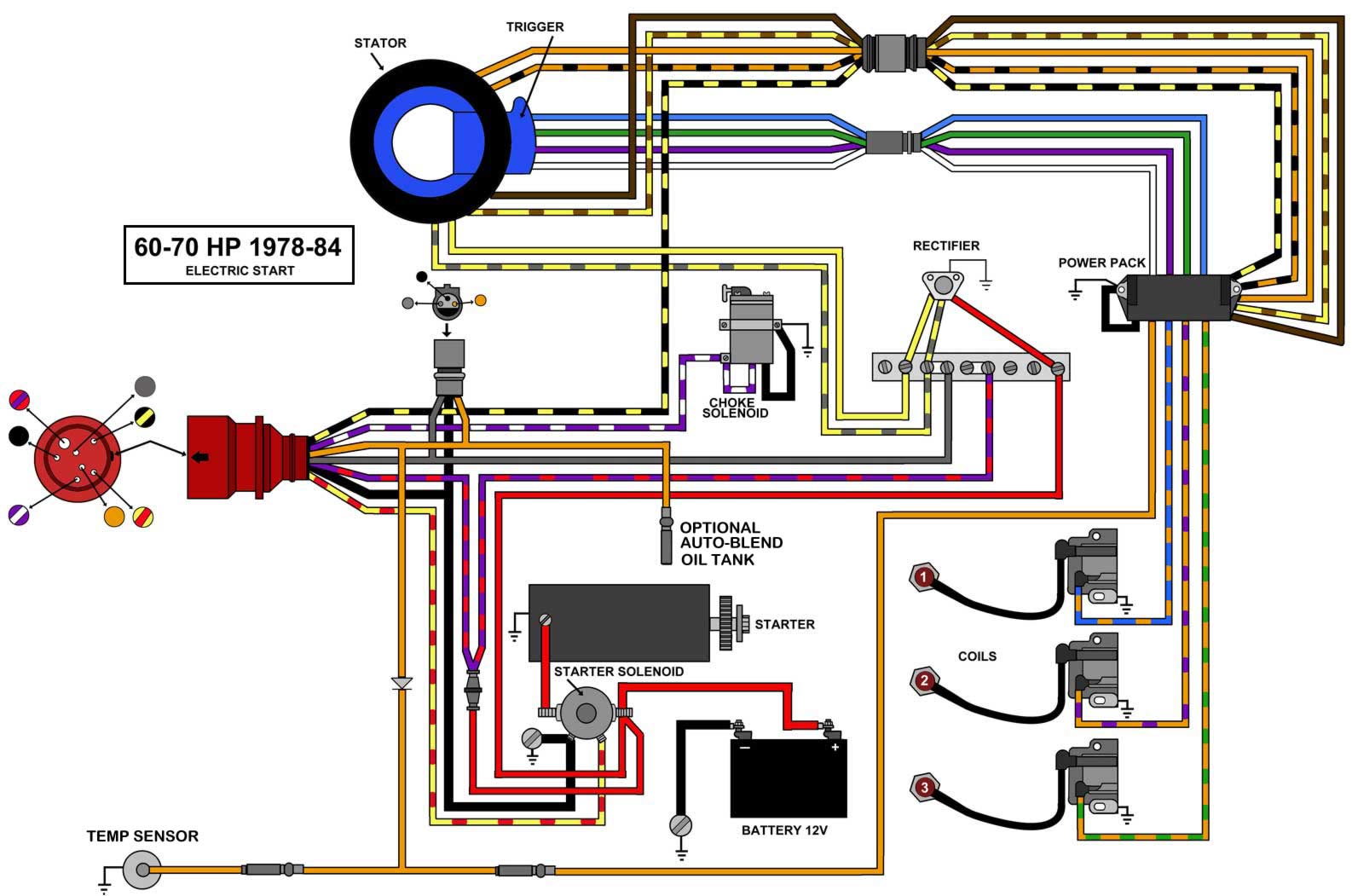
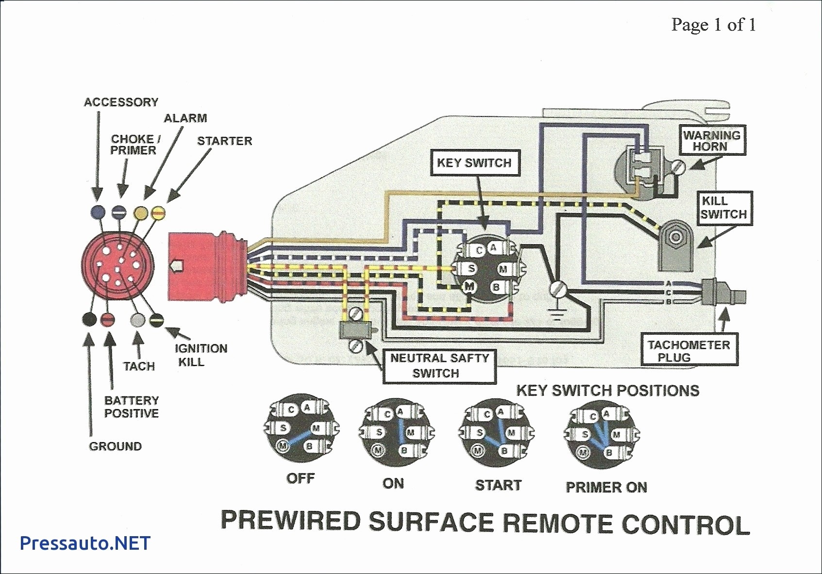
Evinrude Johnson Outboard Wiring Diagrams Mastertech Marine The wiring diagram for the ignition switch of a johnson outboard motor typically shows the connections between the ignition switch, battery, starter motor, and various other electrical components. it provides a visual representation of the electrical pathways within the ignition system, allowing you to easily identify and troubleshoot any issues. Capt. chris of buzzards bay takes a look at a common evinrude johnson ignition switch with integrated clip on safety lanyard (brp part no. 5005801). you'll s.

Evinrude Johnson Outboard Wiring Diagrams Mastertech Marine Hey everyone some one put me onto this web site and i found my diagram. so i thought i would share with everyone because i was looking for a diagram for months. this website has johnson evinrude and most other brands, but the link below is just to the omc diagrams. 1st link the wiring diagrams. choose your year and model. Wiring diagrams for outboard motors. new for 2022! we are building up a repository of free wiring diagrams for outboard motor engines for manufacturers such as johnson, evinrude, mariner, mercury, honda, suzuki, tohahsu and more. troubleshoot your outboard starting or ignition system problems with this essential resource. Gather the necessary tools and materials. before you begin wiring your evinrude ignition system, make sure you have all the tools and materials you need. this includes wire connectors, electrical tape, a wrench or socket set, and the evinrude ignition wiring diagram for your particular model. 2. disconnect the battery. The johnson ignition switch diagram is a useful tool for understanding the electrical wiring and connections of the ignition switch in a johnson outboard motor. this diagram provides a visual representation of how the different components of the ignition system are connected, allowing users to troubleshoot any issues or make modifications as.

Johnson Outboard Ignition Wiring Diagram Gather the necessary tools and materials. before you begin wiring your evinrude ignition system, make sure you have all the tools and materials you need. this includes wire connectors, electrical tape, a wrench or socket set, and the evinrude ignition wiring diagram for your particular model. 2. disconnect the battery. The johnson ignition switch diagram is a useful tool for understanding the electrical wiring and connections of the ignition switch in a johnson outboard motor. this diagram provides a visual representation of how the different components of the ignition system are connected, allowing users to troubleshoot any issues or make modifications as. Symbols such as squares, circles, triangles, and lines are used to indicate switches, fuses, resistors, batteries, and more. understanding these symbols will make it easier to interpret the diagrams. 2. identify the power source. the first step in reading a wiring diagram is to locate the power source. Test the stator and trigger. the stator and trigger are responsible for generating power in your outboard. use a multimeter to test the continuity and resistance of these components. consult the wiring diagram for the correct values. if any readings are outside the recommended range, replace the faulty component. 5.

Wiring Diagram For Johnson Outboard Ignition Switch Database Symbols such as squares, circles, triangles, and lines are used to indicate switches, fuses, resistors, batteries, and more. understanding these symbols will make it easier to interpret the diagrams. 2. identify the power source. the first step in reading a wiring diagram is to locate the power source. Test the stator and trigger. the stator and trigger are responsible for generating power in your outboard. use a multimeter to test the continuity and resistance of these components. consult the wiring diagram for the correct values. if any readings are outside the recommended range, replace the faulty component. 5.

Johnson Outboard Ignition Switch Wiring Diagram

Wiring Diagram For Johnson Outboard Ignition Switch Database Wiring

Comments are closed.