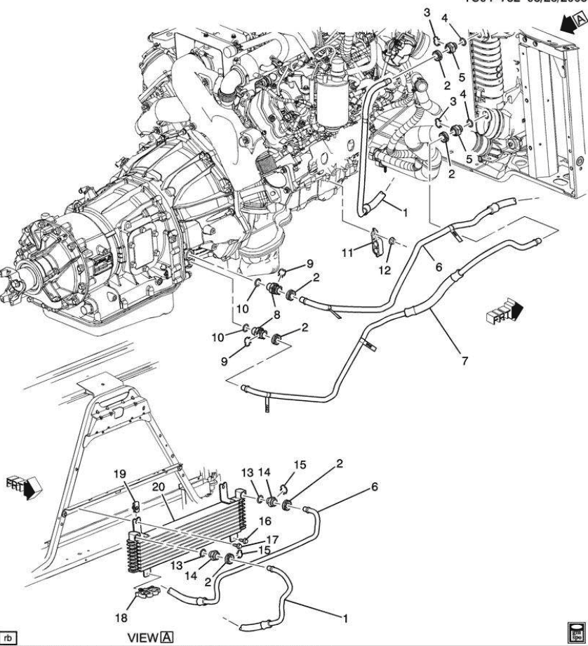
Lmm Duramax Cooling System Diagram

Duramax Transmission Cooler Line Diagram Transmission Cooler Guide Jc1843. 18259 posts · joined 2008. #6 · nov 30, 2016. check with your local part store the may have a coolant pressure tester you can rent borrow so you can pressurize the cooling system that will help you locate the leak. of course you may have to take the air cleaner tube and other items so locate it. Capacities and specifications engine specification engine vin code type 6.6l v8 turbo diesel capacities capacities application english metric cooling system 24.0 quarts 23.0 l automatic transmission 24.0 quarts 23.0 l manual transmission engine oil with filter 10.0 quarts 9.5 l 6.6l v8 all quantities are approximate.
42 Duramax Cooling System Diagram Diagram Resource Diesel site cfikdm coolant filtration system. part# 12345. $170.00. universal. restore the cooling system in your 2007.5 2010 chevy silverado or gmc sierra 2500hd 3500hd 6.6 lmm duramax with a wide selection of parts available at xdp . Coolant is drawn from the radiator outlet and into the water pump inlet by the water pump. the coolant flows to the heater core while the engine is running. this provides the passenger compartment with heat and defrost. coolant is then pumped through the water pump outlet and through the coolant pipe to the engine oil cooler. 3851 posts · joined 2011. #9 · sep 29, 2013. there is a coolant line on both sides of the motor going to the turbo. ive replaced both of mine with 3 8 fuel line and worm gear clamps. ^^ your leak on the passenger side is more than likely that line. they only leak when its running and build pressure. Key components and systems in the lml 6.6 duramax engine diagram: cylinders (numbered) fuel injectors. turbocharger. intercooler. fuel system. cooling system. exhaust system. in summary, the lml 6.6 duramax engine diagram provides a visual representation of the engine’s layout, key components, and systems.

Lmm Duramax Coolant Hose Diagram 3851 posts · joined 2011. #9 · sep 29, 2013. there is a coolant line on both sides of the motor going to the turbo. ive replaced both of mine with 3 8 fuel line and worm gear clamps. ^^ your leak on the passenger side is more than likely that line. they only leak when its running and build pressure. Key components and systems in the lml 6.6 duramax engine diagram: cylinders (numbered) fuel injectors. turbocharger. intercooler. fuel system. cooling system. exhaust system. in summary, the lml 6.6 duramax engine diagram provides a visual representation of the engine’s layout, key components, and systems. In a few, short years the duramax made a name for itself. it was more powerful, capable, and reliable than gm’s previous trucks. when the lly duramax replaced the lb7, it offered several improvements. it also posted improvements in tow capacity, horsepower, and torque. like the lb7, the lly duramax can last a very long time if taken care of. Engines warms to 180* first stage of the primary t stat allowing some flow to the radiator. at 185* secondary t stat starts to open flowing more to the radiator. in here @ arond 132* the turbo starts recieveing coolant through a thermo controlled circuit by pass. at 203* the primary stat is full open.

Comments are closed.