Mammoth Chiller Dry Cooler Wiring Diagram

Mammoth R6gp Wiring Diagram Manualzz Separate field supplied 115 v or 230 v power circuits: terminals 4 and 5 of tb2 are for control of chilled water pump starter. terminals 2 and 3 of tb2 are for alarm. the maximum allowable load for each of these circuits is 125 va sealed. 9. terminal 6 of tb2 is for condenser fan contactor b (hxa) or con source (except 380 415 v units) through. Incoming wire size range for non fused disconnect with mca from 800 to 1199.9 amps is 250 500 kcmil. terminals 9 and 10 of tb5 are for field external connections for remote on off. the contacts must be rated for dry circuit application capable of handling a 24 vac load up to 50 ma.

Industrial Chillers Wiring Diagrams This publication contains wiring diagram information for the 30rb060 390 air cooled liquid chillers with electronic controls. these chillers are equipped with comfortlink™ con trols and electronic expansion valves. note: unit sizes 315 390 are modular units that are shipped in separate sections as modules a or b as noted in position 8 of. Mammoth | literature library. 1 800 422 4328. distributor login. archived products (prior to 2007) download ahri matches. change brand. you can now search for key phrases, document names, and document sku numbers. Holding charge of r 404a on the soda chiller, and dry nitrogen on the ice machine. the system charge is located in the appropriate drink and ice machines. schrader valve fittings table 3. recommended line size in equivalent lengths for r 448a r 449a model max. room max. suction line liquid line. Mammoth brand products are manufactured at our plant in st leonard d’aston, qc, located at: 200 carter st. st leonard d’aston qc j0c 1m0. canada. click for directions. nortek air solutions' mammoth® brand custom packaged dx systems are well known in the hvac industry for their quality, flexibility, and reliability.

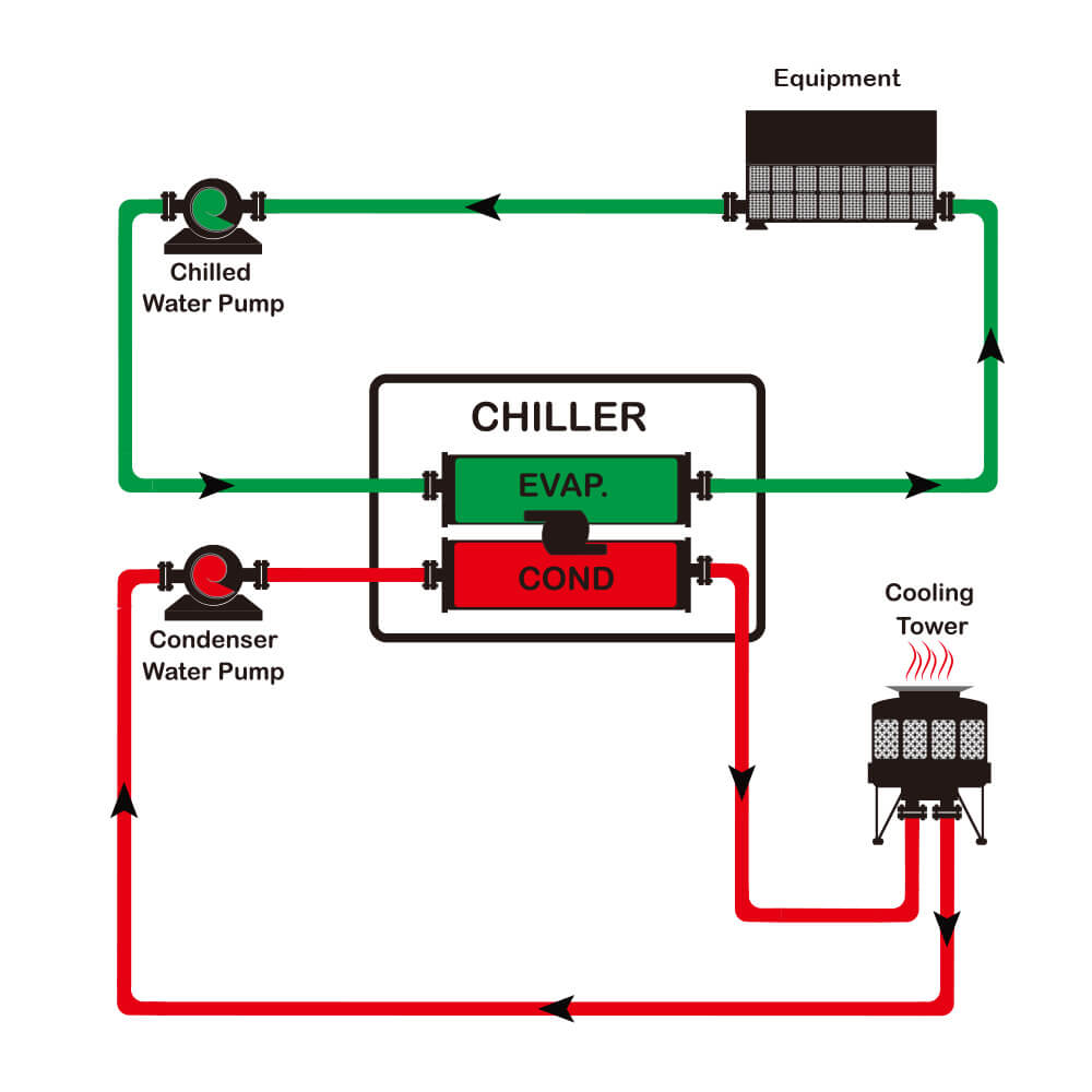
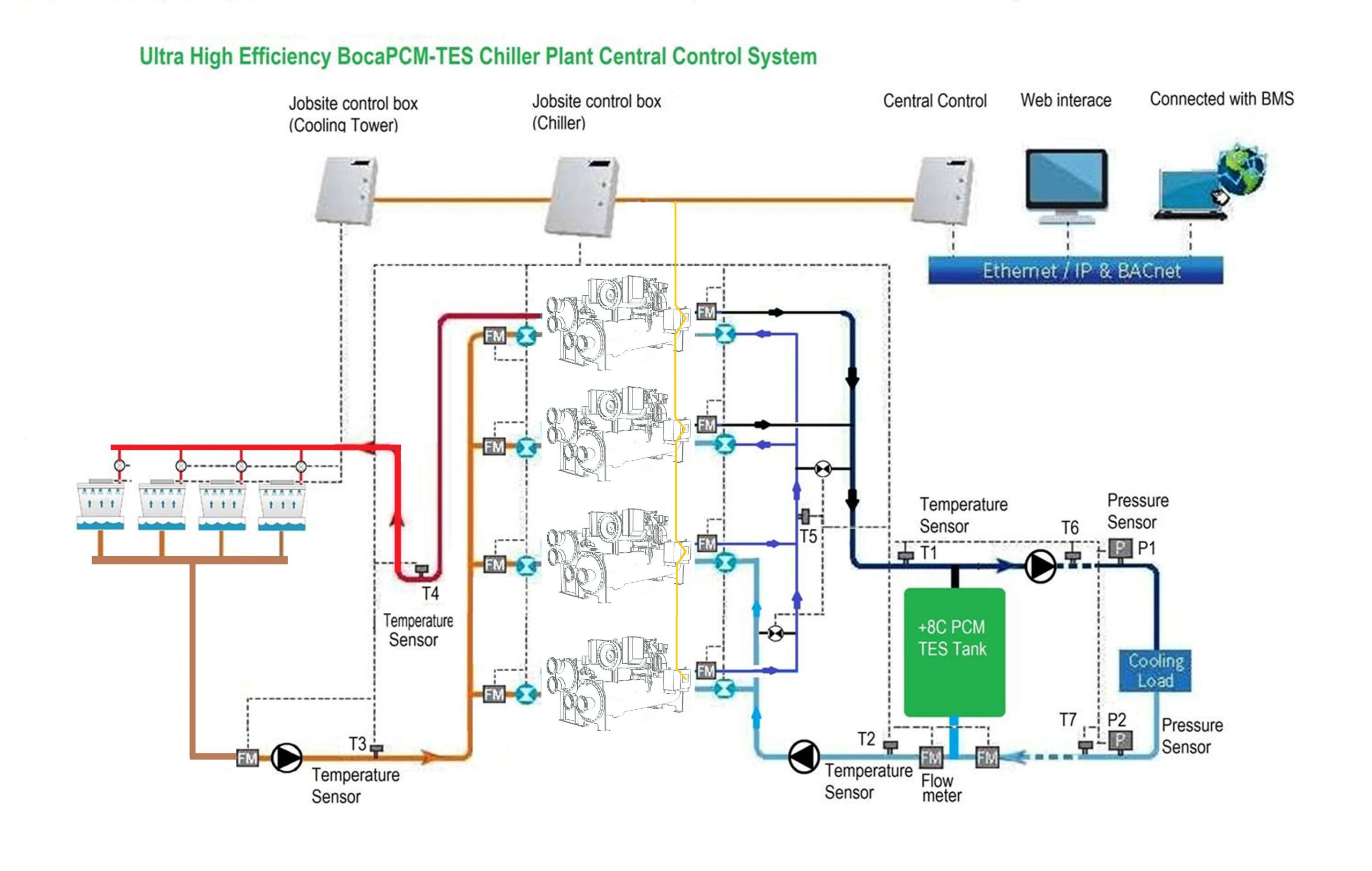
Industrial Chillers Wiring Diagrams Holding charge of r 404a on the soda chiller, and dry nitrogen on the ice machine. the system charge is located in the appropriate drink and ice machines. schrader valve fittings table 3. recommended line size in equivalent lengths for r 448a r 449a model max. room max. suction line liquid line. Mammoth brand products are manufactured at our plant in st leonard d’aston, qc, located at: 200 carter st. st leonard d’aston qc j0c 1m0. canada. click for directions. nortek air solutions' mammoth® brand custom packaged dx systems are well known in the hvac industry for their quality, flexibility, and reliability. The control panel typically includes components such as relays, switches, fuses, and indicators, all of which play a crucial role in monitoring and regulating the chiller’s performance. chiller control wiring diagrams also showcase the various sensors used to measure and monitor key parameters, such as temperature, pressure, and flow rates. The main components of a water cooled chiller include the evaporator, compressor, condenser, expansion valve, water pump, and cooling tower. these components work together to remove heat from the process or system being cooled. the water cooled chiller schematic diagram depicts how the water circulates through these components, absorbing heat.

Chiller System Schematic Diagram Wiring Diagram The control panel typically includes components such as relays, switches, fuses, and indicators, all of which play a crucial role in monitoring and regulating the chiller’s performance. chiller control wiring diagrams also showcase the various sensors used to measure and monitor key parameters, such as temperature, pressure, and flow rates. The main components of a water cooled chiller include the evaporator, compressor, condenser, expansion valve, water pump, and cooling tower. these components work together to remove heat from the process or system being cooled. the water cooled chiller schematic diagram depicts how the water circulates through these components, absorbing heat.

Comments are closed.