Mechanical Drawing Reference

Mechanical Engineering Drawing Symbols Pdf Free Download At A reference dimension is just what it sounds like. it is a dimension shown for reference. in other words it is there for informational purposes only. they are not a requirement in any way. reference dimensions can be used to clarify other dimensions on a drawing. in some instances, they make a drawing easier to understand. The basic drawing standards and conventions are the same regardless of what design tool you use to make the drawings. in learning drafting, we will approach it from the perspective of manual drafting. if the drawing is made without either instruments or cad, it is called a freehand sketch. figure 12 drawing tools. "assembly" drawings.

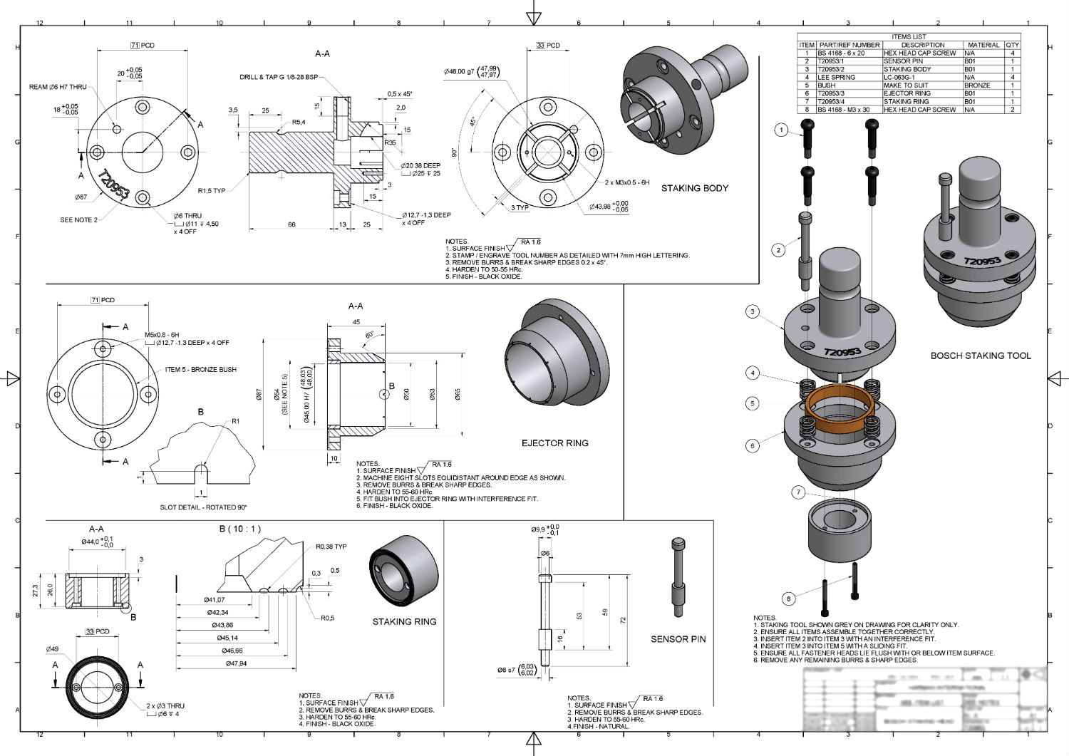
Mechanical Engineering Drawing And Design Everything You Need To Know An engineering drawing provides details such as first angle projections, hidden lines, extension lines, etc., which are crucial for precise manufacturing. they include cross sectional views or an auxiliary view that reveal hidden features and internal details, which a 3d model alone cannot fully convey. while 3d models are valuable for visual. Units of measurement. the units of the print are very important because there is a huge difference between 25.4mm and 25.4 inches. the measurement units will often be called out in the title block or tolerance block but occasionally will be in another section of the blueprint such as in the notes. angular units are important also but there is. To read and interpret engineering drawings effectively, start by examining the title block for important contextual information. familiarize yourself with the purpose, part number, material, finish, and other details provided. next, visualize the assembly in 3d, using isometric views provided in the drawing as a guide. Engineering working drawings basics. engineering graphics is an effective way of communicating technical ideas and it is an essential tool in engineering design where most of the design process is graphically based. engineering graphics is used in the design process for visualization, communication, and documentation.

Mechanical Engineering Drawing Symbols Pdf Free Download At To read and interpret engineering drawings effectively, start by examining the title block for important contextual information. familiarize yourself with the purpose, part number, material, finish, and other details provided. next, visualize the assembly in 3d, using isometric views provided in the drawing as a guide. Engineering working drawings basics. engineering graphics is an effective way of communicating technical ideas and it is an essential tool in engineering design where most of the design process is graphically based. engineering graphics is used in the design process for visualization, communication, and documentation. System, and type of drawing. the drawing number may also contain information such as the sheetnumber,if the drawingis partof a series, or it may containthe revision level. drawings areusuallyfiled by theirdrawing number becaus e thedrawingtitle may be commont o severalprints or series of prints. second area of the title block. An undimensioned drawing is prepared to delineate items that can be fabri cated by use of the patterns to produce the item or to produce a tool for use in fabricating the item. its use as a contour definition drawing provides the definition of contoured surfaces for engineering references and for design of tooling.

30 Mechanical Workings Drawing Reference Ideas Mechanical Design System, and type of drawing. the drawing number may also contain information such as the sheetnumber,if the drawingis partof a series, or it may containthe revision level. drawings areusuallyfiled by theirdrawing number becaus e thedrawingtitle may be commont o severalprints or series of prints. second area of the title block. An undimensioned drawing is prepared to delineate items that can be fabri cated by use of the patterns to produce the item or to produce a tool for use in fabricating the item. its use as a contour definition drawing provides the definition of contoured surfaces for engineering references and for design of tooling.

Mechanical Engineer Drawing At Getdrawings Free Download

Comments are closed.