Mechanical Engineering Drawing And Design Everything You Need To Know

Mechanical Engineering Drawing And Design Everything You Need To Know A good dimension should be easy to read and understand. a dimension should also be accurate and clear. there are different types of dimensions for different purposes. 1.dimensioning should be done in a logical sequence. 2.use the same units of measure, and decimal points, throughout the drawing. The basic drawing standards and conventions are the same regardless of what design tool you use to make the drawings. in learning drafting, we will approach it from the perspective of manual drafting. if the drawing is made without either instruments or cad, it is called a freehand sketch. figure 12 drawing tools. "assembly" drawings.

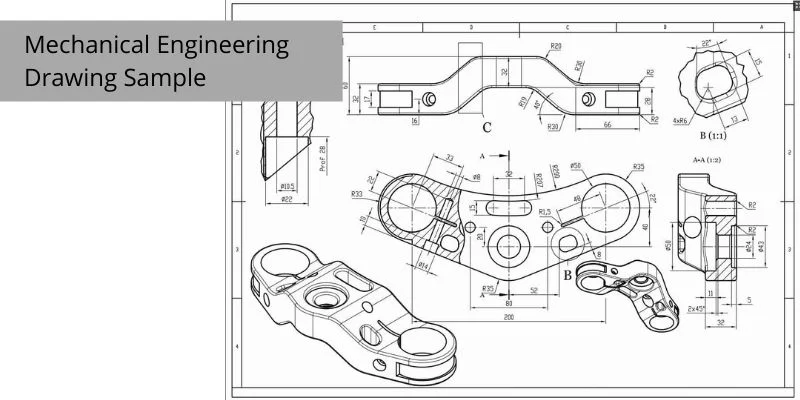
Mechanical Engineering Drawing And Design Everything You Need To Know Here’s a look at some of the most common types of engineering drawings: 1. assembly drawings. these drawings show how multiple parts fit together to form a complete unit. they depict the components of a machine or a system in their relative positions and are essential in guiding the assembly process. Rule 16: unless otherwise specified, when a coordinate system appears on the drawing, it must be right handed. each coordinate axis must be marked and the positive direction indicated. this point is rarely used, so no further detailed explanation is necessary, just follow it. An engineering drawing is a subcategory of technical drawings. the purpose is to convey all the information necessary for manufacturing a product or a part. engineering drawings use standardised language and symbols. this makes understanding the drawings simple with little to no personal interpretation possibilities. An engineering drawing (also named as mechanical drawing, manufacturing blueprints, drawings, dimensional prints, and more) refers to one of the technical drawings, which helps to define engineering products’ requirements. basically, this type of drawing aims at clearly capturing all the geometric features of products and their components.

How To Read Technical Drawing Mechanical Engineering Youtube An engineering drawing is a subcategory of technical drawings. the purpose is to convey all the information necessary for manufacturing a product or a part. engineering drawings use standardised language and symbols. this makes understanding the drawings simple with little to no personal interpretation possibilities. An engineering drawing (also named as mechanical drawing, manufacturing blueprints, drawings, dimensional prints, and more) refers to one of the technical drawings, which helps to define engineering products’ requirements. basically, this type of drawing aims at clearly capturing all the geometric features of products and their components. Engineering drawings serve several important purposes: to communicate design specifications between engineers, manufacturers, and customers. engineering drawings provide all the details needed to manufacture the product to the designer's specifications. to provide a permanent record of the design. the drawing serves as the legal document and. Watch the bonus video on model based definiton and statistical tolerance analysis here! nebula.tv videos the efficient engineer the future of enginee.

Mechanical Engineering Drawing Helpful To Engineering Projects Engineering drawings serve several important purposes: to communicate design specifications between engineers, manufacturers, and customers. engineering drawings provide all the details needed to manufacture the product to the designer's specifications. to provide a permanent record of the design. the drawing serves as the legal document and. Watch the bonus video on model based definiton and statistical tolerance analysis here! nebula.tv videos the efficient engineer the future of enginee.

Detailed Assembly Drawing Buscar Con Google Mechanical Engineering

Engineering Drawing Overview Basic Components Wayken

Comments are closed.