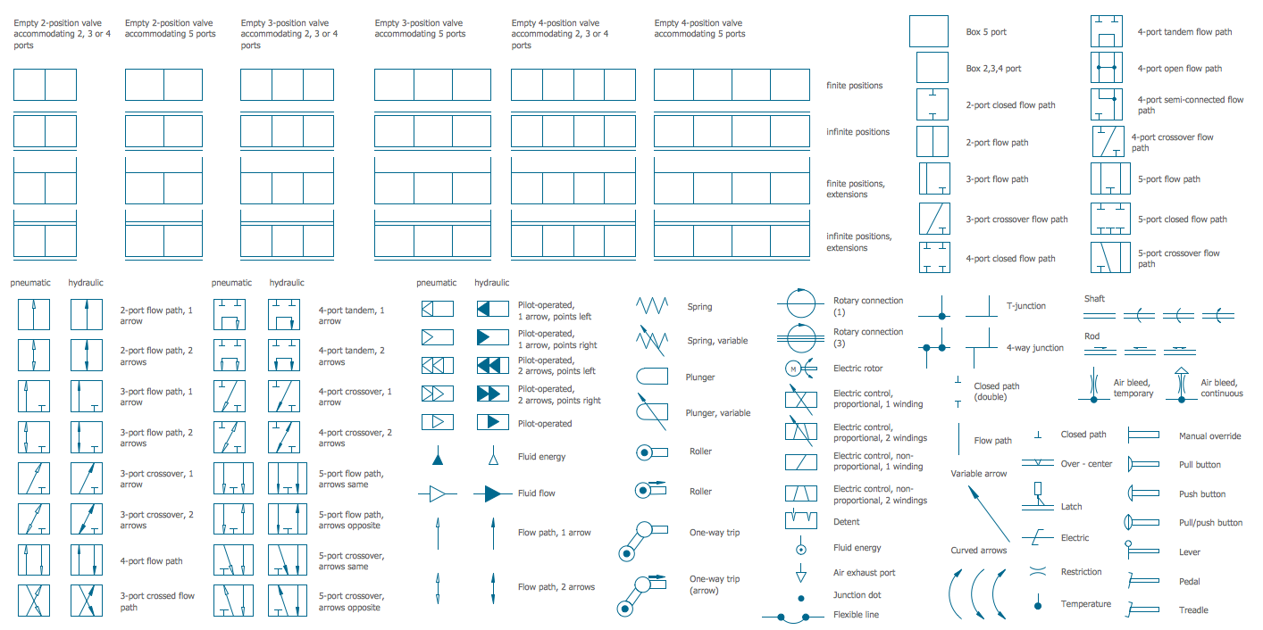
Mechanical Engineering Drawing Symbols Pdf Free Download At Getdrawings

Mechanical Engineering Drawing Symbols Pdf Free Download At 456x482 collection of mechanical engineering drawing pdf free download. 736x1041 447 best autocad design images on technical drawings. 476x515 122 best images on 3d sketch, 3d drawings. 980x744 pampid software. 638x794 machine drawing 83 638 cb=. 640x809 135 best engineering atg images on technology. Of an engineering drawing. eo 1.2 state how the grid system on an engineering drawing is used to locate a piece of equipment. eo 1.3 state the three types of information provided in the revision block of an engineering drawing. eo 1.4 statethe purpose of the notes andlegendsection of an engineering drawing. introduction.

Mechanical Engineering Drawing Symbols Pdf Free Download At Engineering drawing standards manual mechanical engineering branch goddard space flight center greenbelt, maryland august 1994 n a t i o n a l i a e r o n a u t i c s a n d s p a c e a d m i n s t r a t i o u .s a . national aeronautics and space administration goddard space flight center greenbelt, maryland 20771 1994. Drafting symbols symbols provide a “common language” for drafters all over the world. however, symbols can be meaningful only if they are created according to the relevant standards or conventions. this document describes and illustrates common dimensioning, gd&t, architectural, piping, and electrical symbols. standard dimensioning symbols. Figure 2 an isometric drawing. any engineering drawing should show everything: a complete understanding of the object should be possible from the drawing. if the isometric drawing can show all details and all dimensions on one drawing, it is ideal. one can pack a great deal of information into an isometric drawing. Place the t square on the drawing board with the head bearing firmly against the left hand end of the board, as for drawing horizontal lines. place the triangle with one of its edges against the upper edge of the t square, as shown in fig. 5. hold the t square in place by resting the left hand lightly upon the blade.
Mechanical Engineering Drawing Symbols Pdf Free Download At Figure 2 an isometric drawing. any engineering drawing should show everything: a complete understanding of the object should be possible from the drawing. if the isometric drawing can show all details and all dimensions on one drawing, it is ideal. one can pack a great deal of information into an isometric drawing. Place the t square on the drawing board with the head bearing firmly against the left hand end of the board, as for drawing horizontal lines. place the triangle with one of its edges against the upper edge of the t square, as shown in fig. 5. hold the t square in place by resting the left hand lightly upon the blade. Engineering working drawings basics. engineering graphics is an effective way of communicating technical ideas and it is an essential tool in engineering design where most of the design process is graphically based. engineering graphics is used in the design process for visualization, communication, and documentation. Asme y14.24, “drawings types and applications of engineering drawings”, was adopted on. 14 february 2000 for use by the department of defense (dod). proposed changes by dod activities must be submitted to the dod adopting activity: commander, u.s. army ardec, attn: rdar qes e, picatinny arsenal, nj 07806 5000.

Mechanical Engineering Drawing Symbols Pdf Free Download At Engineering working drawings basics. engineering graphics is an effective way of communicating technical ideas and it is an essential tool in engineering design where most of the design process is graphically based. engineering graphics is used in the design process for visualization, communication, and documentation. Asme y14.24, “drawings types and applications of engineering drawings”, was adopted on. 14 february 2000 for use by the department of defense (dod). proposed changes by dod activities must be submitted to the dod adopting activity: commander, u.s. army ardec, attn: rdar qes e, picatinny arsenal, nj 07806 5000.

Comments are closed.