Mercruiser Cooling System Flow Diagram

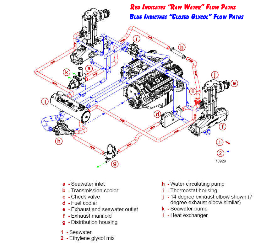
Mercruiser Closed Cooling System Flow Diagram Perfprotech The cooling system in a mercruiser engine consists of several components, including the water pump, thermostat, heat exchanger, and circulating pump. understanding how these components work together to ensure proper coolant flow is crucial for troubleshooting and diagnosing potential problems. the flow of coolant begins with the water pump. Cooling flow diagram: therefore referencing the above flow diagram we want to point out a few of the following mercruiser specific features: reference item “c” check valve – this is a patented feature offered by mercruiser. since mercruiser offers the easy to use single point drain system’s they have to take into account that.

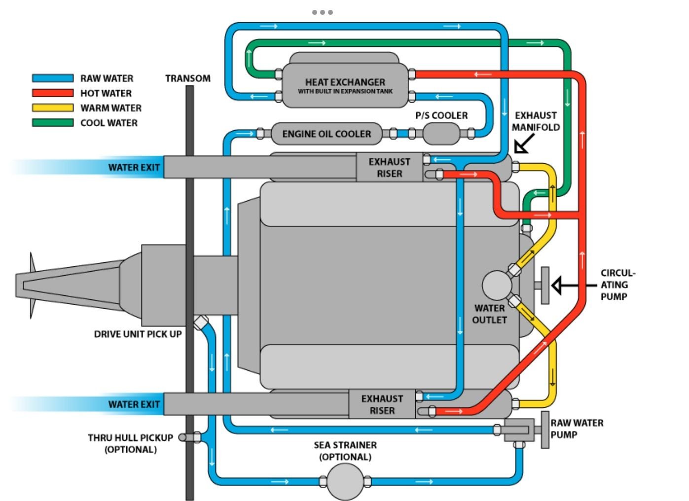
Mercruiser 3 0 Cooling System Diagram Headcontrolsystem The cooling system in the mercruiser 350 mag is designed to regulate the engine’s operating temperature and prevent overheating. it consists of several key components, including the engine block, water pump, thermostat, heat exchanger, and raw water cooling system. each of these components plays a vital role in the overall cooling process. Mercruiser closed cooling system operation. a mercruiser closed cooling system uses a heat exchanger to transfer heat from the engine coolant to the lake or ocean water. this closed loop system eliminates the need for raw water to directly cool the engine, reducing corrosion, scaling, and potential damage from debris. here is a summary of the. Step 2: flush the cooling system. connect the flush kit to the water inlet on the side of your mercruiser engine. turn on the water supply and start the engine. let the engine run for around 10 minutes to flush out any salt, sand, or debris that may be trapped in the cooling system. step 3: drain the cooling system. A mercruiser 5.7 water flow diagram is a visual representation of how water flows through the mercruiser 5.7 engine’s cooling system. this diagram outlines the different components and pathways that the water takes to ensure the engine stays at a proper operating temperature. understanding this diagram is essential for troubleshooting cooling.

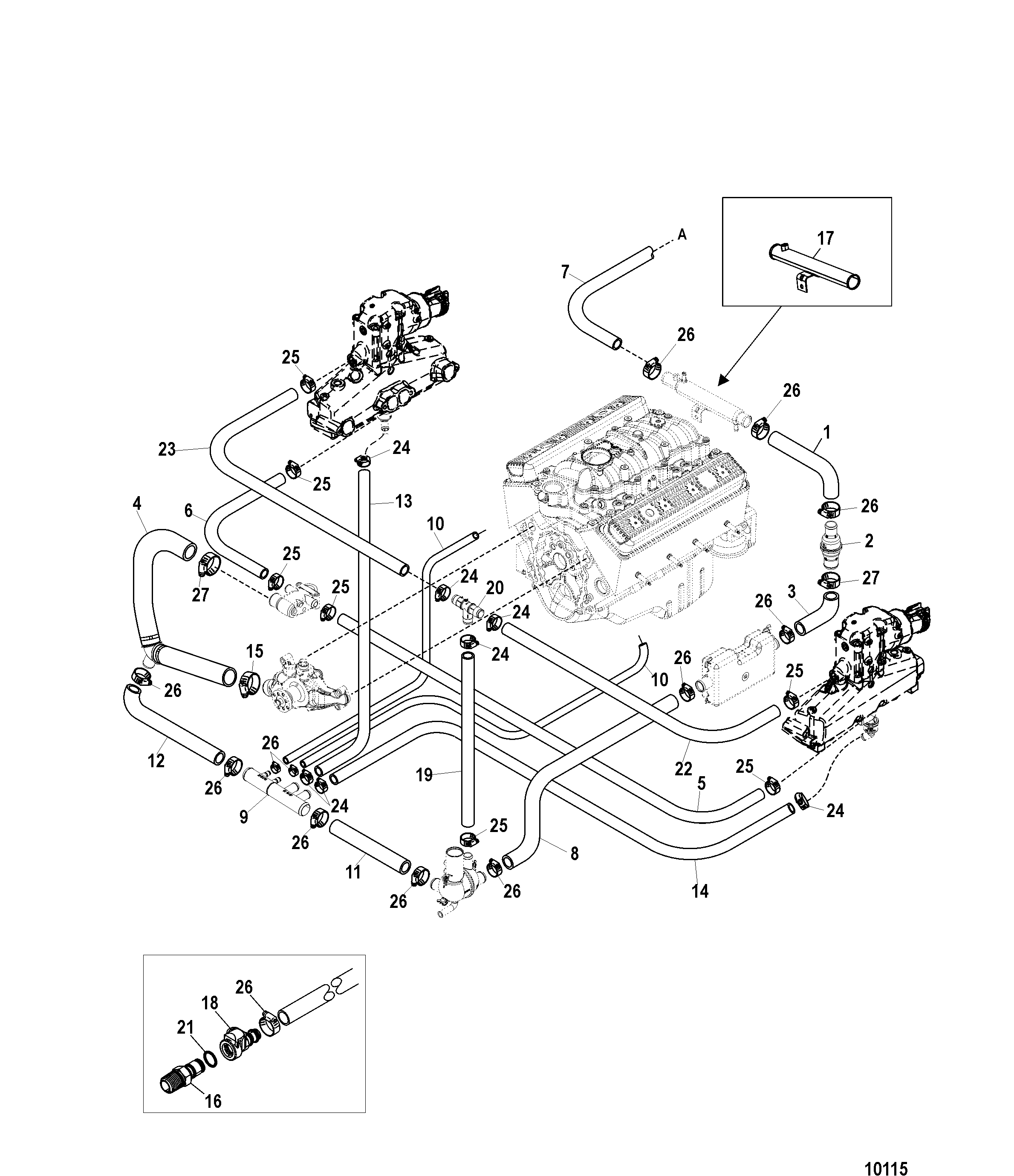
Mercruiser 470 Fresh Water Cooling System Diagram Theme Route Step 2: flush the cooling system. connect the flush kit to the water inlet on the side of your mercruiser engine. turn on the water supply and start the engine. let the engine run for around 10 minutes to flush out any salt, sand, or debris that may be trapped in the cooling system. step 3: drain the cooling system. A mercruiser 5.7 water flow diagram is a visual representation of how water flows through the mercruiser 5.7 engine’s cooling system. this diagram outlines the different components and pathways that the water takes to ensure the engine stays at a proper operating temperature. understanding this diagram is essential for troubleshooting cooling. Note: refer to section 6d ‑ water flow diagrams for full loop and half loop cooling system flow diagrams. sterndrive models with closed cooling alpha models with closed cooling alpha sterndrive models with closed cooling are equipped with a seawater pump on the engine. however, a through‑the‑hull or. For optimum performance, fuel economy and durability. (refer to cooling system flow diagrams at end of section.) to monitor the cooling system, a temperature switch is incorporated into the audio warning system, which alerts the operator of an abnormal condition if the temperature exceeds approximately 93 degrees c (200 degrees f).

Mercruiser Cooling System Flow Chart Note: refer to section 6d ‑ water flow diagrams for full loop and half loop cooling system flow diagrams. sterndrive models with closed cooling alpha models with closed cooling alpha sterndrive models with closed cooling are equipped with a seawater pump on the engine. however, a through‑the‑hull or. For optimum performance, fuel economy and durability. (refer to cooling system flow diagrams at end of section.) to monitor the cooling system, a temperature switch is incorporated into the audio warning system, which alerts the operator of an abnormal condition if the temperature exceeds approximately 93 degrees c (200 degrees f).

Comments are closed.