Mercruiser Engine Cooling Diagram
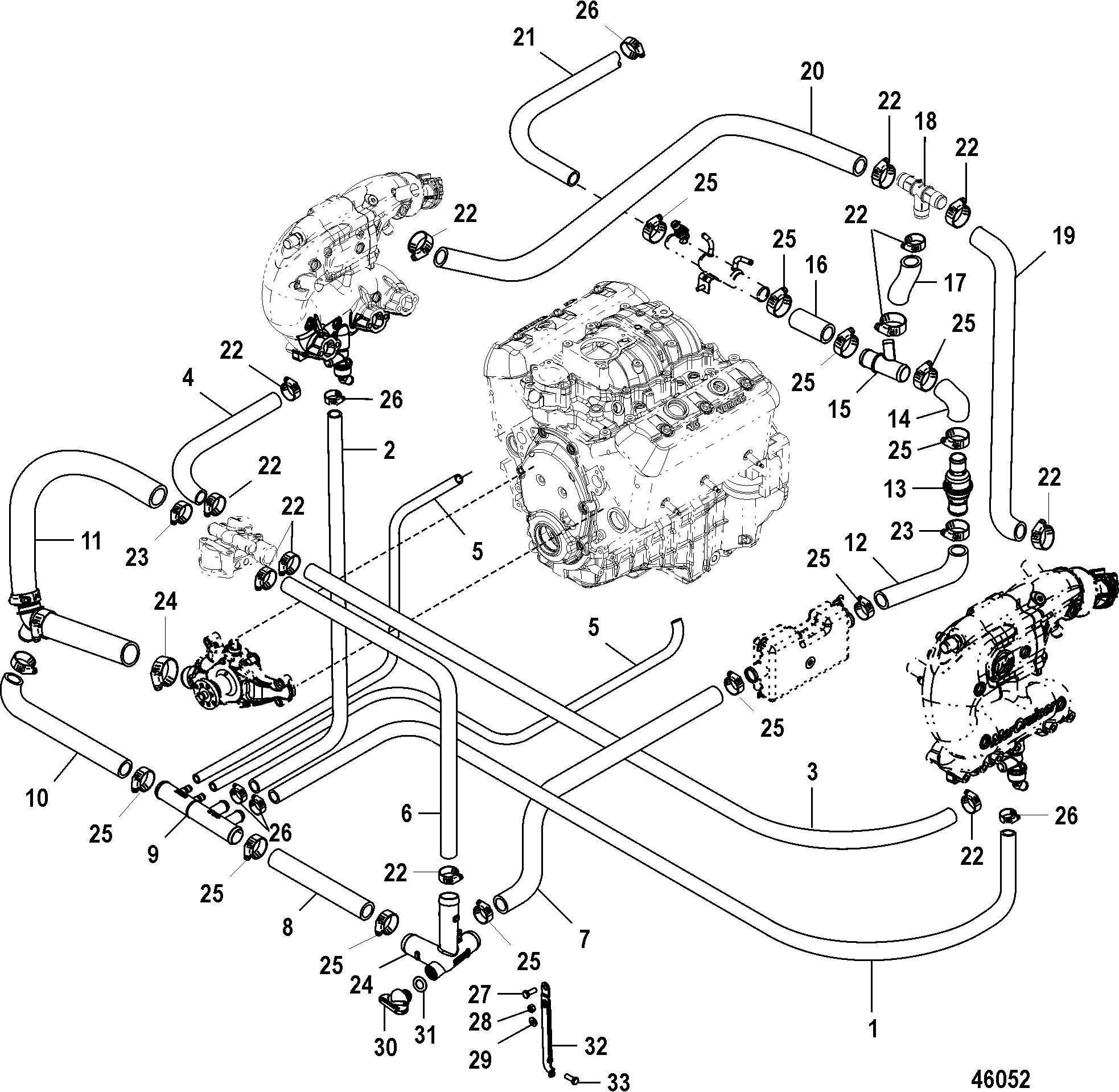
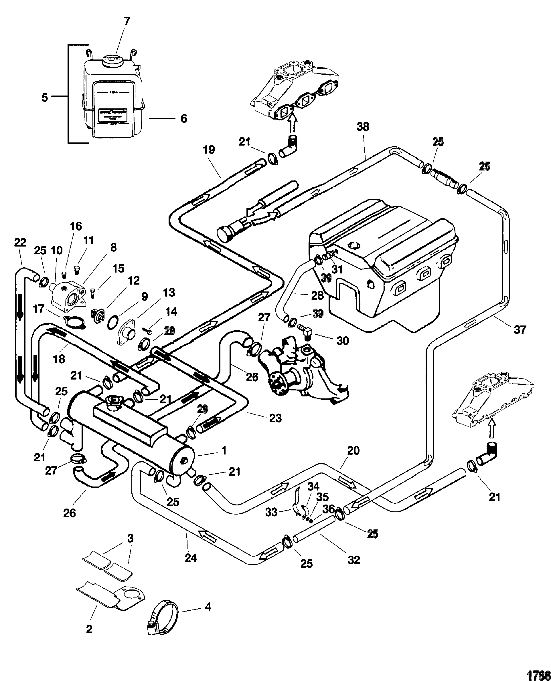
Diagram 7 4 Mercruiser Engine Cooling Diagram Mydiagram Online The cooling system in a mercruiser engine consists of several components, including the water pump, thermostat, heat exchanger, and circulating pump. understanding how these components work together to ensure proper coolant flow is crucial for troubleshooting and diagnosing potential problems. the flow of coolant begins with the water pump. Mercruiser closed cooling system operation. a mercruiser closed cooling system uses a heat exchanger to transfer heat from the engine coolant to the lake or ocean water. this closed loop system eliminates the need for raw water to directly cool the engine, reducing corrosion, scaling, and potential damage from debris. here is a summary of the.

Mercruiser 3 0 Cooling System Diagram The cooling system is an essential component of any marine engine, and the mercruiser 350 mag is no exception. this powerful v8 engine is commonly used in boats and provides reliable power for water sports and cruising. understanding the cooling system diagram can help boat owners and mechanics maintain and troubleshoot any issues that may arise. Step 2: flush the cooling system. connect the flush kit to the water inlet on the side of your mercruiser engine. turn on the water supply and start the engine. let the engine run for around 10 minutes to flush out any salt, sand, or debris that may be trapped in the cooling system. step 3: drain the cooling system. At the heart of the mercruiser 3.0 is its four cylinder in line engine, which delivers reliable power and performance. the diagram provides a visual representation of the engine’s components, from the intake and exhaust systems to the fuel and ignition systems. one of the most critical components highlighted in the diagram is the cooling. Note: refer to section 6d ‑ water flow diagrams for full loop and half loop cooling system flow diagrams. sterndrive models with closed cooling alpha models with closed cooling alpha sterndrive models with closed cooling are equipped with a seawater pump on the engine. however, a through‑the‑hull or.

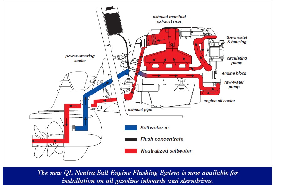
Diagram 7 4 Mercruiser Engine Cooling Diagram Mydiagram Online At the heart of the mercruiser 3.0 is its four cylinder in line engine, which delivers reliable power and performance. the diagram provides a visual representation of the engine’s components, from the intake and exhaust systems to the fuel and ignition systems. one of the most critical components highlighted in the diagram is the cooling. Note: refer to section 6d ‑ water flow diagrams for full loop and half loop cooling system flow diagrams. sterndrive models with closed cooling alpha models with closed cooling alpha sterndrive models with closed cooling are equipped with a seawater pump on the engine. however, a through‑the‑hull or. Page 218 5.0l 305 cid 5.7l 350 cid engines service manual number 24 crankcase front cover oil seal oil seal replacement (without removing front cover) removal 1. remove torsional damper. 2. pry seal out of cover from the front with a large screwdriver. be careful not to distort front cover or damage crankshaft. Understanding the 5.7 mercruiser water flow diagram. the 5.7 mercruiser water flow diagram is an essential tool for understanding how the cooling system of the engine works. it provides a visual representation of the path that water takes throughout the system, ensuring that the engine remains at an optimal operating temperature.

Diagram 7 4 Mercruiser Engine Cooling Diagram Mydiagram Online Page 218 5.0l 305 cid 5.7l 350 cid engines service manual number 24 crankcase front cover oil seal oil seal replacement (without removing front cover) removal 1. remove torsional damper. 2. pry seal out of cover from the front with a large screwdriver. be careful not to distort front cover or damage crankshaft. Understanding the 5.7 mercruiser water flow diagram. the 5.7 mercruiser water flow diagram is an essential tool for understanding how the cooling system of the engine works. it provides a visual representation of the path that water takes throughout the system, ensuring that the engine remains at an optimal operating temperature.

Mercruiser 3 0 Cooling System Diagram

Comments are closed.