Ppt Fe Carbon Diagram Ttt Diagram Heat Treatment Processes

Ppt Fe Carbon Diagram Ttt Diagram Heat Treatment Processes Fe carbon diagram. iron carbon constitutional diagram ii. the following phases are involved in the transformation, occurring with iron carbon alloys: • l liquid solution of carbon in iron; • δ ferrite – solid solution of carbon in iron. maximum concentration of carbon in δ ferrite is 0.09% at 2719 ºf (1493ºc) – temperature of the. Tool steel is generally spheroidized by heating to a temperature of 749° 804°c (1380° 1480°f) for carbon steels and higher for many alloy tool steels, holding at heat from 1 to 4 hours, and cooling slowly in the furnace. download ppt "fe carbon diagram, ttt diagram & heat treatment processes".

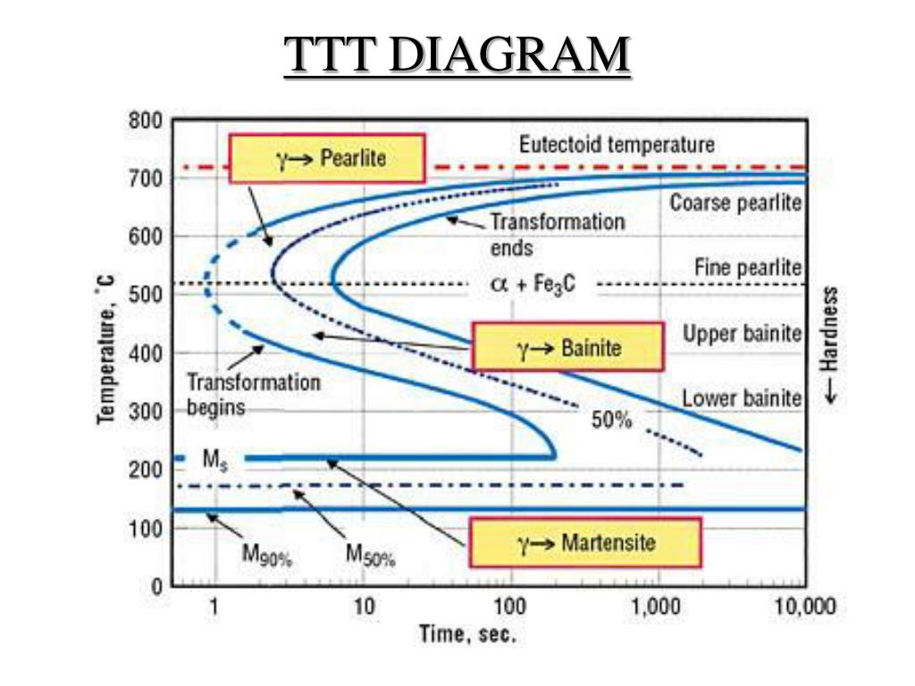
Ppt Fe Carbon Diagram Ttt Diagram Heat Treatment Processes S. saumy agarwal. the document discusses ttt (time temperature transformation) diagrams and heat treatment processes. it explains that ttt diagrams show the structures that form after various cooling rates from the austenite phase. the diagrams graphically depict the cooling rates required to form pearlite, bainite, or martensite. The document discusses the iron iron carbide diagram and heat treatment processes for steels. it provides details on the phases in the fe c diagram including ferrite, cementite, austenite, and pearlite. it also summarizes common heat treatments like full annealing, normalizing, hardening, and tempering. full annealing involves heating above a3. Determination of ttt diagram for eutectoid steel davenport and bain were the first to develop the ttt diagram of eutectoid steel. they determined pearlite and bainite portions whereas cohen later modified and included m s and m f temperatures for martensite. there are number of methods used to determine ttt diagrams. these are salt bath (figs. 1. The document discusses ttt (time temperature transformation) diagrams and heat treatment processes. it explains that ttt diagrams show the structures that form after various cooling rates from the austenite phase. the diagrams graphically depict the cooling rates required to form pearlite, bainite, or martensite.

Ppt Fe Carbon Diagram Ttt Diagram Heat Treatment Processes Determination of ttt diagram for eutectoid steel davenport and bain were the first to develop the ttt diagram of eutectoid steel. they determined pearlite and bainite portions whereas cohen later modified and included m s and m f temperatures for martensite. there are number of methods used to determine ttt diagrams. these are salt bath (figs. 1. The document discusses ttt (time temperature transformation) diagrams and heat treatment processes. it explains that ttt diagrams show the structures that form after various cooling rates from the austenite phase. the diagrams graphically depict the cooling rates required to form pearlite, bainite, or martensite. Presentation on theme: "fe carbon diagram, ttt diagram & heat treatment processes"— presentation transcript: 1 fe carbon diagram, ttt diagram & heat treatment processes presented by: rutash mittal m.e(cim), b.tech(m.e) assistant professor mechanical engineering department, mimit, malout. Introduction. both temperature & time i.e. rate of cooling is taken in consideration. ttt – time temperature transformation. a plot of temperature versus log of time. steel alloy of definite composition. determines when transformations begin and end for an isothermal (constant temp.) phase transformation of a previously austenitized alloy.

Ppt Fe Carbon Diagram Ttt Diagram Heat Treatment Processes Presentation on theme: "fe carbon diagram, ttt diagram & heat treatment processes"— presentation transcript: 1 fe carbon diagram, ttt diagram & heat treatment processes presented by: rutash mittal m.e(cim), b.tech(m.e) assistant professor mechanical engineering department, mimit, malout. Introduction. both temperature & time i.e. rate of cooling is taken in consideration. ttt – time temperature transformation. a plot of temperature versus log of time. steel alloy of definite composition. determines when transformations begin and end for an isothermal (constant temp.) phase transformation of a previously austenitized alloy.

Ppt Fe Carbon Diagram Ttt Diagram Heat Treatment Processes

Comments are closed.