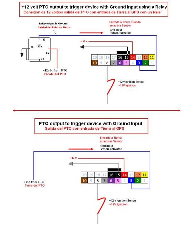
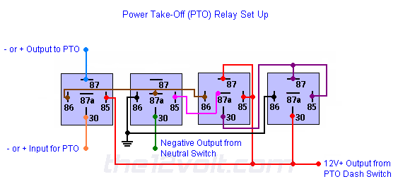
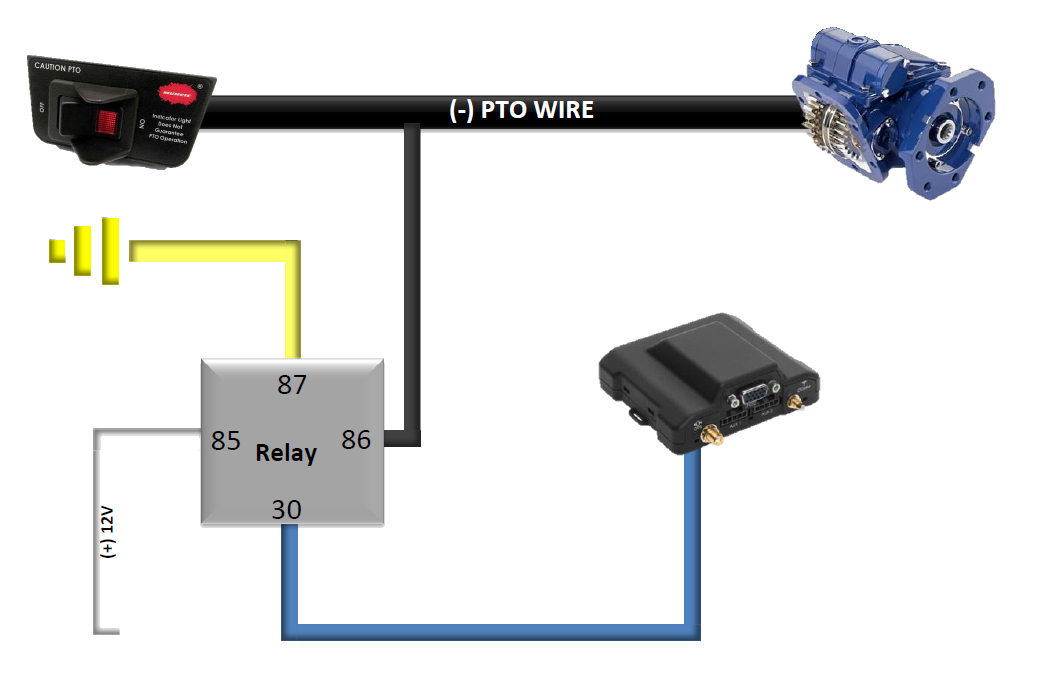
Pto Hyd Cooler Relay Wiring Diagram

2017 Ford F550 Pto Wiring Diagram When using a direct mount method, in pto installation, use a support bracket to support the pump to the transmission when the following conditions apply: the pump weight 40 pounds or more; the combined length of the pto and pump reaches or exceeds 18 inches from the pto centerline to the end of the pump. The 2" × 3" pto equipped caution label is to be placed within the cab of the vehicle and in easy view of the vehicle operator. it should be located . near the pto control, when the control is installed in the vehicle dash. see figure 2. this label directs the operator to read the pto operating instructions on the “visor label”.

Pto Wiring Schematic Wiring Diagram And Schematic A. important: disconnect battery prior to installing electric hydraulic activation kits. b. locate the wiring harness provided with your fr6* 3c pto. separate the harness at the 4 wire connector. c. the engine compartment section has the connection to the pto activation solenoid and pressure switch. make the connection to both components. Follow installation instructions for fr series pto in03 01 until step 41. locate a 12v dc source in under the dash and connect the fused red wire. locate a battery ground and attach the black wire with the ring terminal to the ground. Remember to attach all warning decals and labels to the visor and dash. good solid crimps are important. check to make sure you have good secure crimps. it takes 20 pounds to pull off a good crimp for 18 gage wire. soldering is the prefer method. twisting wires together and black tape is never recommended. 2 installing the pto & hyd pump 2 3 electrical wiring 3 4 4 hydraulic plumbing 5 6 5 final assembly 7 6 start up procedures 8 system maintenance 9 troubleshooting10 specifications11 ss bk934er parts breakdown 12 ss bk934ev parts breakdown 13 ss bk934hr parts breakdown 14 ss bk934hv parts breakdown 15 ss bk934e parts breakdown 16.

Diagram Jd L130 Pto Wiring Diagram Mydiagram Online Remember to attach all warning decals and labels to the visor and dash. good solid crimps are important. check to make sure you have good secure crimps. it takes 20 pounds to pull off a good crimp for 18 gage wire. soldering is the prefer method. twisting wires together and black tape is never recommended. 2 installing the pto & hyd pump 2 3 electrical wiring 3 4 4 hydraulic plumbing 5 6 5 final assembly 7 6 start up procedures 8 system maintenance 9 troubleshooting10 specifications11 ss bk934er parts breakdown 12 ss bk934ev parts breakdown 13 ss bk934hr parts breakdown 14 ss bk934hv parts breakdown 15 ss bk934e parts breakdown 16. Work the nut flush with the hous ing making sure that the gasket is in position while turning the nut. tighten the upper left nut so that it is flush with the housing. install the remaining 2 capscrews and tighten to approximately 30 ft.lbs. install the 3 8" hex nuts on the two remaining studs. 3 general information general information split shaft (muncie) † through torque to 21,600 lb ft. † output torque to 936 lb ft. † 1410 or 1500 series companion flange outputs.

Pto Wiring Schematic Wiring Diagram And Schematic Work the nut flush with the hous ing making sure that the gasket is in position while turning the nut. tighten the upper left nut so that it is flush with the housing. install the remaining 2 capscrews and tighten to approximately 30 ft.lbs. install the 3 8" hex nuts on the two remaining studs. 3 general information general information split shaft (muncie) † through torque to 21,600 lb ft. † output torque to 936 lb ft. † 1410 or 1500 series companion flange outputs.

Power Take Off Pto Two Inputs One Output Only Once Relay Wiring

Overview Guide Relays Device Help

Comments are closed.