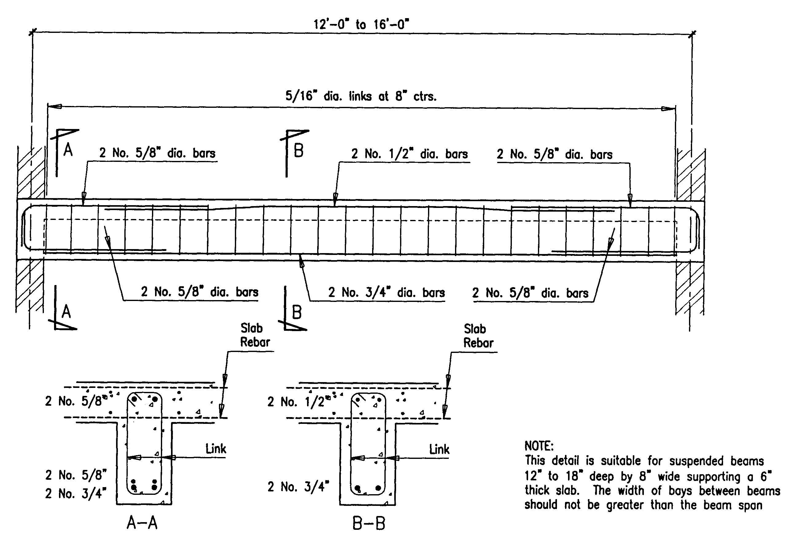
Reinforced Concrete Beam Column End Support Detail

Reinforced Concrete Beam Column End Support Detail Concrete Column 92)details and detailing199. the rights of. crete industry are stated more clearly by providing. specifications for . 315 highway bridges,” pg. (in.) for standard end hooks on grade 60 bars in. (in.) for standard end hooks on grade 60 bars in. 1.3 engineering drawings buildings and other struc . Reinforced concrete beam column end support detail. be the first to leave a review. € 4.00. great generic drawing ready to be used in all projects. one of the most useful reinforcement details when designing for concrete structures. beam to column end support reinforcement detail.

Reinforced Concrete Beam Column End Support Detail Concrete Column Typical detailing of a reinforced concrete beam. the technical guides to the detailing and arrangement of beam reinforcements are as follows; (1) confirm the formwork dimensions and stability. beam reinforcement placement commences immediately after the carpenters complete the soffit formwork of the floor. The size of the column is not restricted to allow the use of small concrete column cross section in lightly loaded concrete structure, as per aci 318 19. however, is 456 specifies a minimum column size of 228 mm x 228 mm, contains steel reinforcement of 4 bars of 12 mm supported laterally by stirrups of 8 mm diameter at a distance of 150 mm. Simply supported beam analysis and design – spbeam software. spbeam is widely used for analysis, design and investigation of beams, and one way slab systems (including standard and wide module joist systems) per latest american (aci 318 14) and canadian (csa a23.3 14) codes. spbeam can be used for new designs or investigation of existing. The structural design of reinforced concrete (r.c.) columns involves the provision of adequate compression reinforcement and member size to guaranty the stability of the structure. in typical cases, columns are usually rectangular, square, or circular in shape. other sections such as elliptical, octagonal, etc are also possible.

Typical Reinforcement Details Of Perimeter Beams Reinforced Concrete Simply supported beam analysis and design – spbeam software. spbeam is widely used for analysis, design and investigation of beams, and one way slab systems (including standard and wide module joist systems) per latest american (aci 318 14) and canadian (csa a23.3 14) codes. spbeam can be used for new designs or investigation of existing. The structural design of reinforced concrete (r.c.) columns involves the provision of adequate compression reinforcement and member size to guaranty the stability of the structure. in typical cases, columns are usually rectangular, square, or circular in shape. other sections such as elliptical, octagonal, etc are also possible. We need to calculate the max. bending moment and shear force for our governing uls load and the bending moment due to our quasi permanent load, before we can design the reinforced concrete beam. design load applied to simply supported concrete beam. uls max bending moment. m d = 54.6 k n m ⋅ l 2 8 = 334.4 k n m. Clearly, the detailing of the reinforced concrete members is the key to good design and execution of work at the site.that is why poor detailing of reinforcement makes the structure undergo cracking, excessive deflection, or even collapse. reinforcements resist tensile forces. they may also be required in the compression zones to increase the.

Reinforced Concrete Beam Column End Support Detail We need to calculate the max. bending moment and shear force for our governing uls load and the bending moment due to our quasi permanent load, before we can design the reinforced concrete beam. design load applied to simply supported concrete beam. uls max bending moment. m d = 54.6 k n m ⋅ l 2 8 = 334.4 k n m. Clearly, the detailing of the reinforced concrete members is the key to good design and execution of work at the site.that is why poor detailing of reinforcement makes the structure undergo cracking, excessive deflection, or even collapse. reinforcements resist tensile forces. they may also be required in the compression zones to increase the.

Building Guidelines Drawings Section B Concrete Construction

Comments are closed.