Schematic Diagram Of A Cooling Tower

Cooling Tower Diagram A Go To Guide To Learn About Their Function The cooling tower return pipework is installed to transport the warm water from the condenser side of the water cooled chiller to the cooling tower, with the flow being provided by the condenser water pumps that are installed on the supply side of the tower [tower to chiller] to move the water around the system. return pipework configuration. Counterflow cooling tower diagram difference between crossflow and counterflow cooling towers: in counterflow cooling tower system processes, the air vertically flows upwards, counter to the water flow in the fill media. due to the air flowing vertically, it's not possible to use the basin's gravity flow like in crossflow towers.

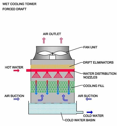
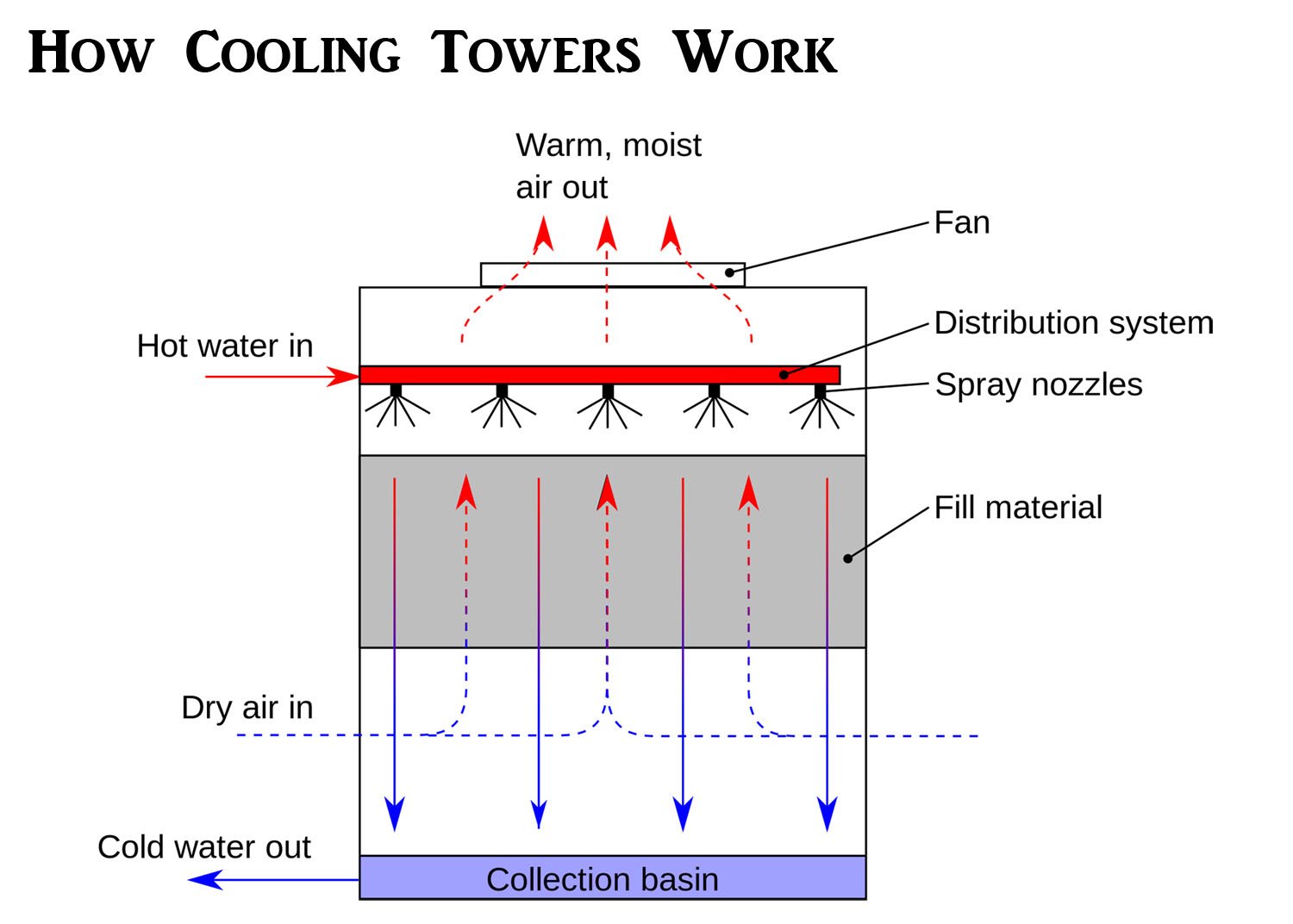
How Cooling Towers Work W Diagram Pictures Principles 2018 The water is flashed to air as it passes throughout the cooling tower. the air has been pulled using a motor driven electrical "cooling tower fan". when the air and water come into the contact, a little amount of water dissipates, producing a cooling operation. and again the cold water is pumped back to the machine that incorporates heat or the. A cooling tower schematic diagram is a visual representation of how a cooling tower works. it shows the different components of a cooling tower and how they interact to remove heat from a system. cooling towers are commonly used in industrial and commercial settings to cool down heated water or other fluids. in the diagram, you can see the main. Sequence of operation. when the operating fan(s) are operating at 50 percent speed, an additional fan shall be enabled and controlled at the same speed as the operating fans until all active cooling tower cell fans are enabled. when operating fans are running at minimum speed and the tower supply water temperature is five (5) degrees below the. Section 1 – evaporative cooling towers an evaporative cooling tower is a heat exchanger that transfers heat from circulating water to the atmosphere. warm water from the heat source is pumped to the top of the tower and then flow down through plastic or wooden shells. as it falls downward . cooling towers – m07 001 3.
Schematic Drawing Showing The Basic Components Of A Cooling Tower Sequence of operation. when the operating fan(s) are operating at 50 percent speed, an additional fan shall be enabled and controlled at the same speed as the operating fans until all active cooling tower cell fans are enabled. when operating fans are running at minimum speed and the tower supply water temperature is five (5) degrees below the. Section 1 – evaporative cooling towers an evaporative cooling tower is a heat exchanger that transfers heat from circulating water to the atmosphere. warm water from the heat source is pumped to the top of the tower and then flow down through plastic or wooden shells. as it falls downward . cooling towers – m07 001 3. The water is exposed to air as it flows throughout the cooling tower. the air is being pulled by an motor driven electric “cooling tower fan”. when the air and water come together, a small volume of water evaporates, creating an action of cooling. the colder water gets pumped back to the process equipment that absorbs heat or the condenser. Cooling towers are commonly of the induced draft, cross flow variety, although counter flow and forceddraft cooling towers are also represented. the cooling towers range in size from small to large capacity. 1.4 comp onents of a cooling tower. figure 10 shows a simple diagram of a 1 fan, induced draft, cross flow cooling tower.

Comments are closed.