Shear Diagram Triangular Distributed Load

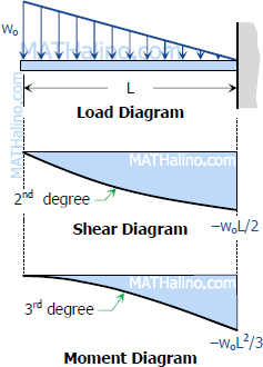
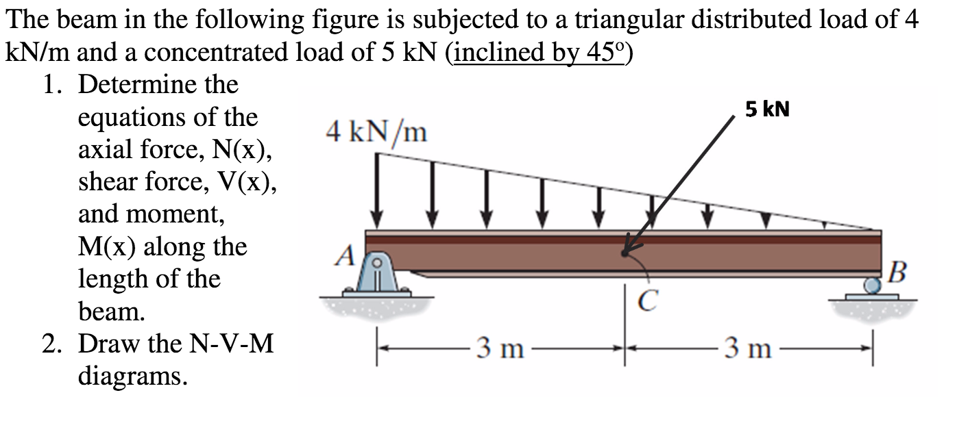
Triangular Distributed Load In Shear And Bending Moment Diagrams In 3 Figure 7: distributed and concentrated loads. consider a simply supported beam carrying a triangular and a concentrated load as shown in figure 7. for the purpose of determining the support reaction forces \(r 1\) and \(r 2\), the distributed triangular load can be replaced by its static equivalent. the magnitude of this equivalent force is. Shear and bending moment diagrams for a beam subjected to a triangular distributed load. triangular distributed loadpoint loadsdistributed loadsexternal coup.

Triangular Distributed Load Shear And Moment Diagram General Wiring Figures 1 through 32 provide a series of shear and moment diagrams with accompanying formulas for design of beams under various static loading conditions. shear and moment diagrams and formulas are excerpted from the western woods use book, 4th edition, and are provided herein as a courtesy of western wood products association. Arch 331 169 of note set 8.2 su2015abn. 1. simple beam— shear uniformly distributed load total equiv. uniform load w w12 wx 5 w14 384 el x) 4. m max. simple beam— shear uniform load partially ri = vi max. when a < c ra = va max. when a > c when x a and < m max. at x distributed (2c b) 21 21 ri —w (x—a). If distributed load is 0, then the shear will be constant and the slope of the moment will be linear (as shown in example 1 in the next section). for the derivation of the relations among w, v , and m , consider a simply supported beam subjected to a uniformly distributed load throughout its length, as shown in the figure below. In each problem, let x be the distance measured from left end of the beam. also, draw shear and moment diagrams, specifying values at all change of loading positions and at points of zero shear. neglect the mass of the beam in each problem. solution 417. v = lw 4 w x 2 l is a second degree curve; at x = 0, v = lw 4; at x = l 2, v = 0.

Triangular Distributed Load Shear And Moment Diagram Free Diagram For If distributed load is 0, then the shear will be constant and the slope of the moment will be linear (as shown in example 1 in the next section). for the derivation of the relations among w, v , and m , consider a simply supported beam subjected to a uniformly distributed load throughout its length, as shown in the figure below. In each problem, let x be the distance measured from left end of the beam. also, draw shear and moment diagrams, specifying values at all change of loading positions and at points of zero shear. neglect the mass of the beam in each problem. solution 417. v = lw 4 w x 2 l is a second degree curve; at x = 0, v = lw 4; at x = l 2, v = 0. Equation 6.1 suggests the following expression: Δm = ∫ v (x)dx Δ m = ∫ v (x) d x (equation 6.2) equation 6.2 states that the change in moment equals the area under the shear diagram. similarly, the shearing force at section x dx is as follows: v x dx = v −wdx v dv = v − wdx v x d x = v − w d x v d v = v − w d x. or. Uniformly distributed load (udl): this type of load is evenly distributed along the length or width of a structure. it can be represented graphically as a straight line on a shear and moment diagram. triangular distributed load: this type of load varies linearly along the length or width of a structure, forming a triangular shape when graphed.

Triangular Distributed Load Shear And Moment Diagram Wiring Diagram Equation 6.1 suggests the following expression: Δm = ∫ v (x)dx Δ m = ∫ v (x) d x (equation 6.2) equation 6.2 states that the change in moment equals the area under the shear diagram. similarly, the shearing force at section x dx is as follows: v x dx = v −wdx v dv = v − wdx v x d x = v − w d x v d v = v − w d x. or. Uniformly distributed load (udl): this type of load is evenly distributed along the length or width of a structure. it can be represented graphically as a straight line on a shear and moment diagram. triangular distributed load: this type of load varies linearly along the length or width of a structure, forming a triangular shape when graphed.

Triangular Load Shear And Moment Diagram

Shear And Moment Diagrams For Distributed Loads

Comments are closed.