Solidworks Snap Drawing Line To Reference Axis

Creating A Reference Axis In Solidworks Youtube To set sketch snaps: click options or click tools > options. select relations snaps. select or clear enable snapping to affect all sketch snaps. under sketch snaps, select or clear the appropriate sketch snap. using quick snaps from the menu, the shortcut menu, or the pull down toolbar, you can override any sketch snap that is cleared under. Reference geometry in a model is hidden by default when you create drawing views. however, if you insert reference geometry with insert model items, entities of the selected types are shown. when you insert reference geometry into drawings, axes, and points are shown in gray. surfaces are shown as visible lines (black). to toggle the display.

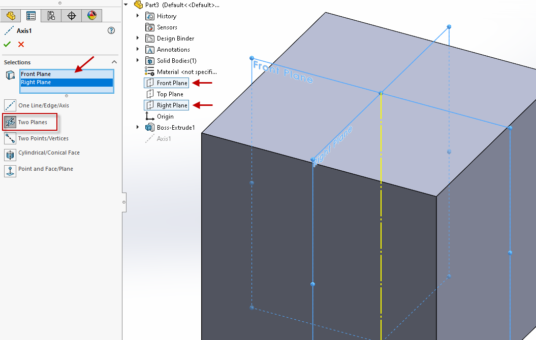
Solidworks Basics Of Reference Geometry Axis Currently, it seems like i only have two reasonable options to define its location:< p><p>1) draw a line in a 3d sketch and dimension it from the origin.< p><p>2) create extra reference planes points that will be solely used for setting the axis' location.< p><p>< p><p>i want the axis to be prominent in the feature tree so i don't want to bury. The reference axis will be created coincident to the point and normal to the face or plane. in all scenarios, the reference axis will show up as a feature in your featuremanager design tree. i hope this gives you a better understanding of ways to create a reference geometry axis to make you more efficient in solidworks! nicole kelley. To snap to the grid, you’ll need to check the “grid” box under the “sketch snaps” heading. the “snap only when grid is displayed” checkbox below determines whether you can snap to the grid at all times or only when it is visible. with the grid settings enabled, you can utilize the snap points of the grid lines as you’re sketching. As by ahmad shumayal 06 26 20. i want to draw the axis1 but with 2d sketch or 3d sketch. i have done it before by snapping to the centre of the circles on either side of the cylinder but for the life of my i can't do it anymore. all my snap settings in system options are checked. i tried sketching on the plane that is a reference of the axis1.

Creating A Solidworks Reference Plane At An Angle To snap to the grid, you’ll need to check the “grid” box under the “sketch snaps” heading. the “snap only when grid is displayed” checkbox below determines whether you can snap to the grid at all times or only when it is visible. with the grid settings enabled, you can utilize the snap points of the grid lines as you’re sketching. As by ahmad shumayal 06 26 20. i want to draw the axis1 but with 2d sketch or 3d sketch. i have done it before by snapping to the centre of the circles on either side of the cylinder but for the life of my i can't do it anymore. all my snap settings in system options are checked. i tried sketching on the plane that is a reference of the axis1. To activate snapping in the sketch: open the “options” dialog box. (tools => options) the dialog box will open and the “system options” tab will be selected automatically. click on the “relations snaps” under the “sketch” on the left pane. turn on the “enable snapping” checkbox as shown in the figure. click “ok” to apply. The most common type of reference plane is an offset plane. to create an offset plane, select the reference geometry drop down on the commandmanager and choose the plane option. once the option to create a plane is open, select a face or another plane and set a distance for the offset. (figure 1 & 2) there is also the option to create multiple.

Solidworks How To Create Reference Axis Youtube To activate snapping in the sketch: open the “options” dialog box. (tools => options) the dialog box will open and the “system options” tab will be selected automatically. click on the “relations snaps” under the “sketch” on the left pane. turn on the “enable snapping” checkbox as shown in the figure. click “ok” to apply. The most common type of reference plane is an offset plane. to create an offset plane, select the reference geometry drop down on the commandmanager and choose the plane option. once the option to create a plane is open, select a face or another plane and set a distance for the offset. (figure 1 & 2) there is also the option to create multiple.

Comments are closed.