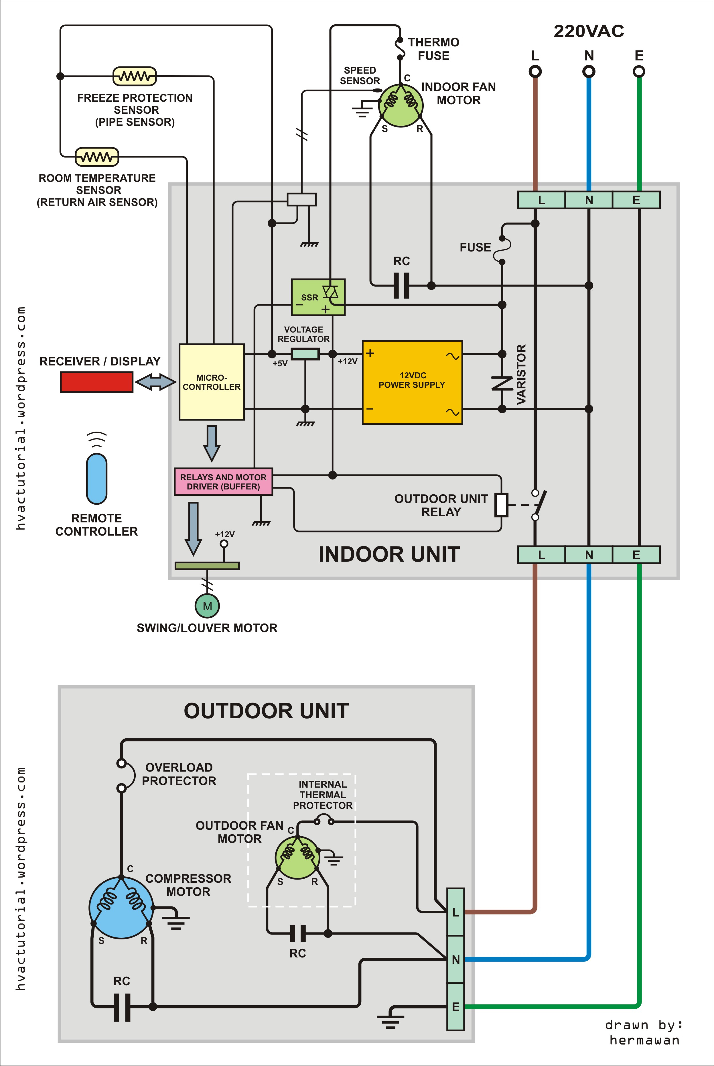
Straight Cool Wiring Diagram

Straight Cool Air Conditioning Schematic Carrier Youtube Bryan walks through a schematic of a carrier straight cool air conditioning system. he shows exactly how the real system lines up with the connection diagram and the ladder schematic. before getting started, bryan pulls the disconnect and ensures that there is no power to the unit during the demonstration. the connection diagram and schematic. Bryan walks through a schematic of a carrier straight cool air conditioning system. he shows exactly how the real system lines up with the connection diagram.

Straight Cool Wiring Diagram R or rc wire (power) connected to the r power terminal to power the thermostat. w wire (heat), connected to the heating control. g wire (fan) connected to the fan control to operate a blower in your hvac system. y1 wire (cooling) connected to the y terminal compressor refrigerant system. Kalos gm jesse goes over the straight cool setup & wiring of a honeywell focuspro thermostat for a basic a c system.the red wire goes on the r terminal, and. Page 1: wiring diagrams. 38aks013 024 air cooled condensing units 50 60 hz wiring diagrams units produced after january 1996 index electrical schematic component label diagram unit characteristics diagram arrangement (on unit) 38aks (v ph hz) fig. no. fig. no. no. 38ak 208 230 3 60 501206 380 3 60 501206 230 3 50 501206 013 024. 1 importance of electrical wiring for air conditioning systems. in the detailed design phase, the electrical designer must size and select the wires cables, conduits, starters, disconnects and switchgear necessary for supplying power and control to hvac equipment. this information designed by the electrical designer will be and must appear on.

Straight Cool Air Handler Wiring Diagram Page 1: wiring diagrams. 38aks013 024 air cooled condensing units 50 60 hz wiring diagrams units produced after january 1996 index electrical schematic component label diagram unit characteristics diagram arrangement (on unit) 38aks (v ph hz) fig. no. fig. no. no. 38ak 208 230 3 60 501206 380 3 60 501206 230 3 50 501206 013 024. 1 importance of electrical wiring for air conditioning systems. in the detailed design phase, the electrical designer must size and select the wires cables, conduits, starters, disconnects and switchgear necessary for supplying power and control to hvac equipment. this information designed by the electrical designer will be and must appear on. Here’s how to wire a thermostat using the color code and, fyi, each terminal’s purpose. attach the red wire to the r terminal (call for heating and or cooling). attach the green wire to the g terminal (fan). attach the white wire to the w terminal (heat). attach the yellow wire to the y terminal (ac). 1Ø schematic diagram 1. use copper wire (75ºc min) only between disconnect switch and unit. 2. to be wired in accordance with n.e.c. and local codes. 3. if any of the original wire, as supplied, must be replaced, use the same or equivalent type wire. 4. red wire white stripe to qc1a, blk wire white stripe to qc2a. 5.

Comments are closed.