Thermostat Wire Colors Explained Wiring Diagram

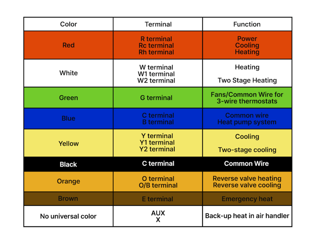
Thermostat Wire Colors Explained Here’s how to wire a thermostat using the color code and, fyi, each terminal’s purpose. attach the red wire to the r terminal (call for heating and or cooling). attach the green wire to the g terminal (fan). attach the white wire to the w terminal (heat). attach the yellow wire to the y terminal (ac). These control the power, heat and fan. standard thermostats use 4 or 5 wires: r, w, g, y, and sometimes c. these control the power, heat, fan, and cooling. more advanced thermostats use 6 8 wires. the extra wires control additional hvac system features and settings, signaling a two stage cooling or heat pump system.

Thermostat Wiring 101 How To Wire A Thermostat For Your Home Yellow wires. the yellow wires on your thermostat connect to your compressor. they control your air conditioning system by turning the compressor on and off. the yellow wires connect your thermostat to your compressor contactor via the air handler. the yellow wires connect to the y terminals on your thermostat. Mostly for new digital thermostats that require continuous power via c wire. typical 6 wire thermostats will use red (r or rc or rh), white (w, w1), yellow (y, y1), green (g), black or blue c wire, and orange (o b) wire for reversing valve switch; used for complex heat pumps. thermostat wire color meanings are standardized. The most common configuration of a 4 wire thermostat is: red, r wire: this carries the 24v power supply and is responsible for the functioning of the thermostat and communicating with the hvac system. insert it into the r or rc terminal. white, w wire: this is the heating wire and signals the heating system. Unscrew the two wires from the terminals. remove the motherboard of the old 2 wire thermostat and put the new 2 wire thermostat in its place. reconnect the red and white wire, tighten down the set screw, and put the control panel back on. test the 2 wire thermostat wiring by turning the furnace on.

Thermostat Wire Colors Explained Wiring Diagram The most common configuration of a 4 wire thermostat is: red, r wire: this carries the 24v power supply and is responsible for the functioning of the thermostat and communicating with the hvac system. insert it into the r or rc terminal. white, w wire: this is the heating wire and signals the heating system. Unscrew the two wires from the terminals. remove the motherboard of the old 2 wire thermostat and put the new 2 wire thermostat in its place. reconnect the red and white wire, tighten down the set screw, and put the control panel back on. test the 2 wire thermostat wiring by turning the furnace on. G – green: this wire controls the blower motor in the furnace. y2 – light blue: this wire is necessary if you have a two stage ac compressor. if the ac is single stage, this terminal will be empty. w2 – light brown: this wire functions like the light blue wire but for furnaces with low and high stages of heating. G – green: fan – this is for the blower in the air handler. r – red: 24 volt power – your air handler is powered by 110v, but it is converted to 24v for the thermostat. c – blue: common wire for continuous 24 volt power from the thermostat to the air handler. e – white (optional): emergency heat.

Comments are closed.