Thermostat Wiring Diagram

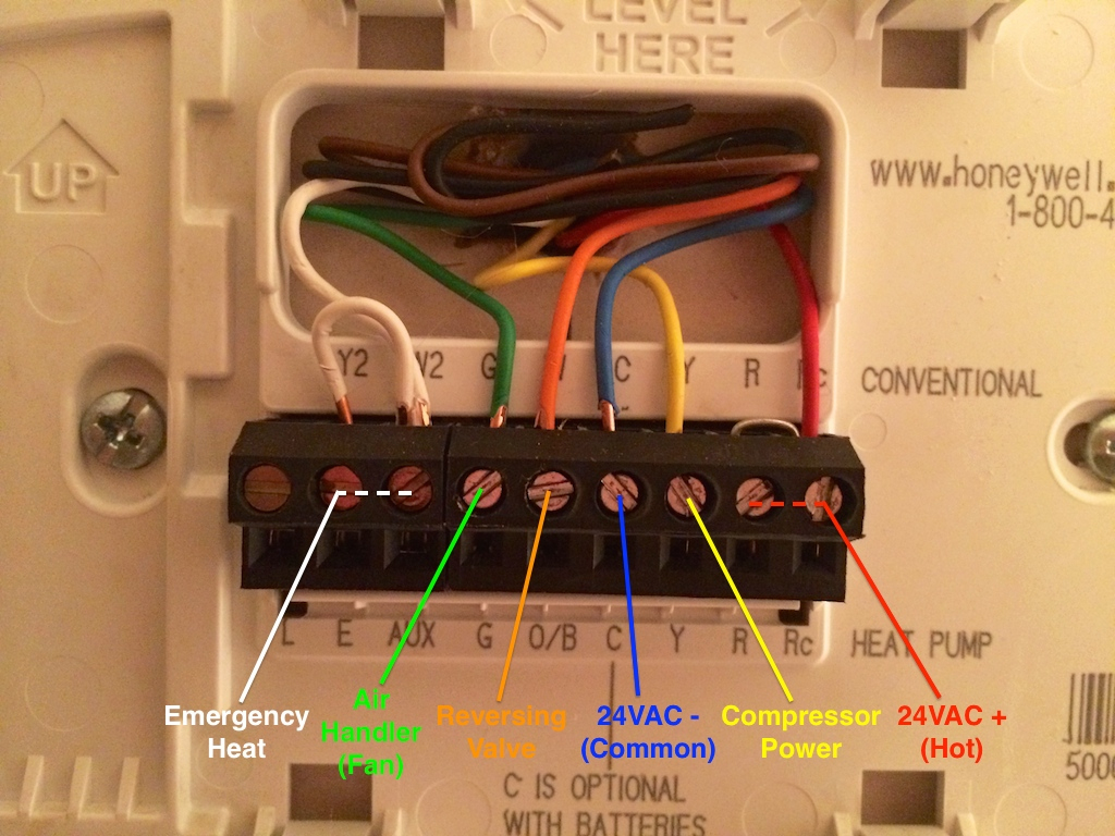
Thermostat Wiring Explained These control the power, heat and fan. standard thermostats use 4 or 5 wires: r, w, g, y, and sometimes c. these control the power, heat, fan, and cooling. more advanced thermostats use 6 8 wires. the extra wires control additional hvac system features and settings, signaling a two stage cooling or heat pump system. Here’s how to wire a thermostat using the color code and, fyi, each terminal’s purpose. attach the red wire to the r terminal (call for heating and or cooling). attach the green wire to the g terminal (fan). attach the white wire to the w terminal (heat). attach the yellow wire to the y terminal (ac).

Room Thermostat Wiring Diagrams For Hvac Systems 4 Wire Thermostat Learn how to install a new thermostat in your home with this guide. find out the industry standard color code for thermostat wires and how to locate the common wire for smart thermostats. Learn how to wire a thermostat for different hvac devices such as furnaces, air conditioners, and heat pumps. find out the color codes and functions of each wire, and see diagrams and examples for each type of thermostat. Learn how to wire thermostats for air conditioners, heat pumps, and furnaces with these diagrams and color codes. find out the differences between heat pumps and air conditioners, and how to use smart thermostats with wifi and apps. Learn how to identify your type of thermostat, the different types of wires, and what each wire controls. follow the steps to remove and install a new thermostat with a photo guide and tips.

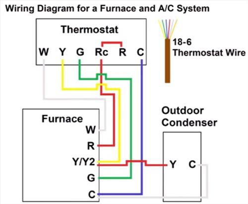
Typical Wiring Diagram For Thermostat Wiring Diagram Learn how to wire thermostats for air conditioners, heat pumps, and furnaces with these diagrams and color codes. find out the differences between heat pumps and air conditioners, and how to use smart thermostats with wifi and apps. Learn how to identify your type of thermostat, the different types of wires, and what each wire controls. follow the steps to remove and install a new thermostat with a photo guide and tips. Furnace wiring diagram. this gas furnace wiring diagram is a guide to wiring most thermostats that will control a gas furnace system whether or not it includes an ac unit. you might not need all the wires. various system configurations and thermostat wiring including 4 wire, 5 wire and 7 wire thermostats are discussed on this page. How to wire a thermostat thermostat wiring diagram. this thermostat wiring diagram is a split system. these split systems include an air conditioner with a gas furnace, oil furnace, or electric furnace. furthermore, the wires going to the condensing unit are shown in red and white. however, these colors can be different.

Thermostat Wiring Colors To Labels Thermostat Wiring Hvac Thermostat Furnace wiring diagram. this gas furnace wiring diagram is a guide to wiring most thermostats that will control a gas furnace system whether or not it includes an ac unit. you might not need all the wires. various system configurations and thermostat wiring including 4 wire, 5 wire and 7 wire thermostats are discussed on this page. How to wire a thermostat thermostat wiring diagram. this thermostat wiring diagram is a split system. these split systems include an air conditioner with a gas furnace, oil furnace, or electric furnace. furthermore, the wires going to the condensing unit are shown in red and white. however, these colors can be different.

Thermostat Wiring To A Furnace And Ac Unit Color Code How It Works

Robertshaw 9520 Thermostat Wiring Diagram Wiring Diagram

Comments are closed.