Thermostat Wiring To A Furnace And Ac Unit Color Code How It Works Diagram

Thermostat Wiring For Ac These control the power, heat and fan. standard thermostats use 4 or 5 wires: r, w, g, y, and sometimes c. these control the power, heat, fan, and cooling. more advanced thermostats use 6 8 wires. the extra wires control additional hvac system features and settings, signaling a two stage cooling or heat pump system. In this hvac installation training video, i show how to wire the low voltage thermostat wires into a furnace and ac unit. i explain what each of the letter t.

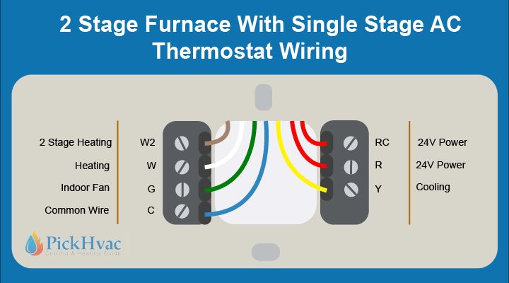
Thermostat Wiring To A Furnace And Ac Unit Color Code How It Works Here’s how to wire a thermostat using the color code and, fyi, each terminal’s purpose. attach the red wire to the r terminal (call for heating and or cooling). attach the green wire to the g terminal (fan). attach the white wire to the w terminal (heat). attach the yellow wire to the y terminal (ac). Mostly for new digital thermostats that require continuous power via c wire. typical 6 wire thermostats will use red (r or rc or rh), white (w, w1), yellow (y, y1), green (g), black or blue c wire, and orange (o b) wire for reversing valve switch; used for complex heat pumps. thermostat wire color meanings are standardized. Furnace wiring diagram. this gas furnace wiring diagram is a guide to wiring most thermostats that will control a gas furnace system whether or not it includes an ac unit. you might not need all the wires. various system configurations and thermostat wiring including 4 wire, 5 wire and 7 wire thermostats are discussed on this page. The 4 wire thermostat color code includes a red wire that works for power (24v), a white wire—connected to a “w” or ”w1” terminal—that works for heating, a green wire that works for fan, and a yellow or sky blue wire—connected to a “y” terminal—that works for cooling. wire a 4 wire thermostat following these steps:.

Furnace Thermostat Wire Colors Furnace wiring diagram. this gas furnace wiring diagram is a guide to wiring most thermostats that will control a gas furnace system whether or not it includes an ac unit. you might not need all the wires. various system configurations and thermostat wiring including 4 wire, 5 wire and 7 wire thermostats are discussed on this page. The 4 wire thermostat color code includes a red wire that works for power (24v), a white wire—connected to a “w” or ”w1” terminal—that works for heating, a green wire that works for fan, and a yellow or sky blue wire—connected to a “y” terminal—that works for cooling. wire a 4 wire thermostat following these steps:. The difference between 2 wire and 3 wire thermometer is the “g” or green wire that is usually used for fans. in the 3 wire thermostat wiring, the green wire serves as a repurposed c or “common” wire. here is the 3 wire thermostat wiring color code: red wire for power (24v). white wire for heating (connected to w or w1 terminal). The most common configuration of a 4 wire thermostat is: red, r wire: this carries the 24v power supply and is responsible for the functioning of the thermostat and communicating with the hvac system. insert it into the r or rc terminal. white, w wire: this is the heating wire and signals the heating system.

Gas Electric Furnace Thermostat Wiring Diagrams Color Code The difference between 2 wire and 3 wire thermometer is the “g” or green wire that is usually used for fans. in the 3 wire thermostat wiring, the green wire serves as a repurposed c or “common” wire. here is the 3 wire thermostat wiring color code: red wire for power (24v). white wire for heating (connected to w or w1 terminal). The most common configuration of a 4 wire thermostat is: red, r wire: this carries the 24v power supply and is responsible for the functioning of the thermostat and communicating with the hvac system. insert it into the r or rc terminal. white, w wire: this is the heating wire and signals the heating system.

Comments are closed.