Three View Drawing Reference Template

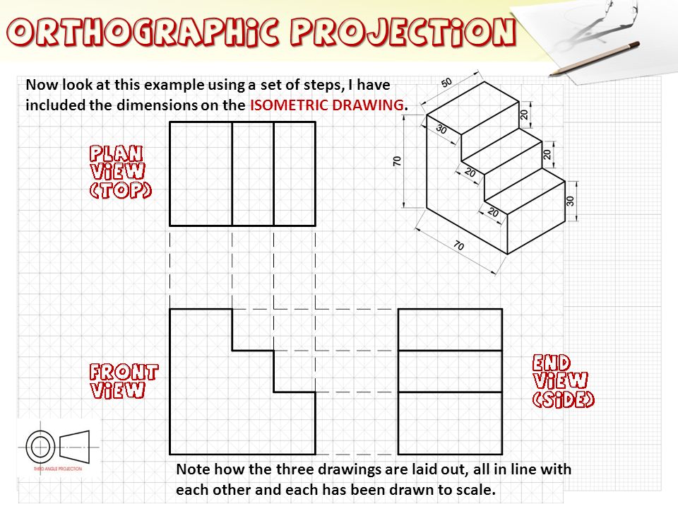
Three View Orthographic Drawing At Paintingvalley Explore Block. a three view drawing will most clearly show the appearance as well as the exact size and other details of construction of an object. the three view drawing of the concrete block shown in fig. 2 2 is a drawing with the top view posi tioned directly above the front view and the right side or left side view positioned directly to the right. Drawing with three point perspective. start by marking your horizon line and placing your three vanishing points—two along the horizon and one either above or below it, depending on your viewpoint. the third point radically changes the view, creating a sensation of height or depth. next, draw a line from the third vanishing point to define.

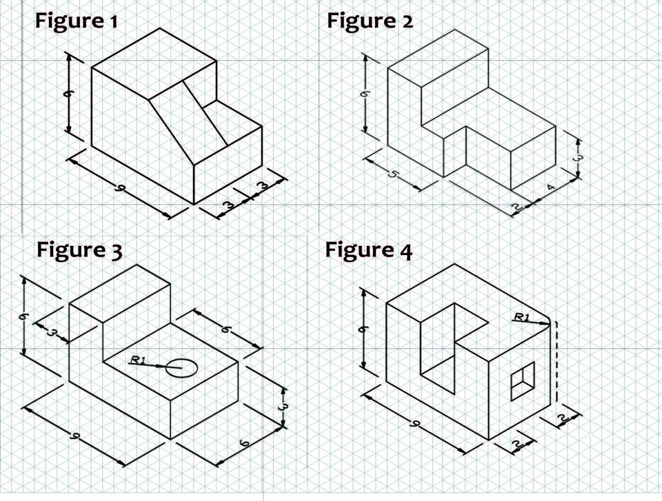
Three View Orthographic Drawing At Getdrawings Free Download The representation of the object in figure 2 is called an isometric drawing. this is one of a family of three dimensional views called pictorial drawings. in an isometric drawing, the object’s vertical lines are drawn vertically, and the horizontal lines in the width and depth planes are shown at 30 degrees to the horizontal. Identify views used in technical drawings including perspective, isometric, oblique, orthographic, plans, elevations, and sections. architectural drawings are made according to a set of conventions, which include particular views (floor plan, section, etc.), sheet sizes, units of measurement and scales, annotation, and cross referencing. Rotate projection move view: switch between the ability to rotate the grid and the ability to track sideways. (this only works on the non embedded version on geogebra.org. a dynamic 3 point perspective grid with adjustable rotation, and field of view. excellent for use as the foundation for drawings, paintings or industrial design renderings. An isometric drawing allows you to sketch the depth of an object. the glass box projections produced six views: top, front, right side, left side, rear, and bottom. in almost all objects, three views standard drawing views are adequate to describe it. the three standard views are the top, front, and right side.

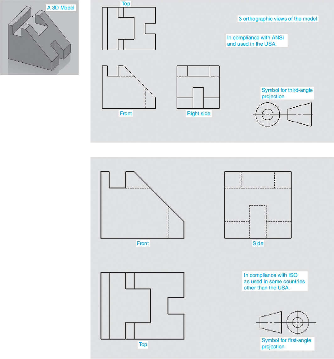
Three View Orthographic Drawing At Paintingvalley Explore Rotate projection move view: switch between the ability to rotate the grid and the ability to track sideways. (this only works on the non embedded version on geogebra.org. a dynamic 3 point perspective grid with adjustable rotation, and field of view. excellent for use as the foundation for drawings, paintings or industrial design renderings. An isometric drawing allows you to sketch the depth of an object. the glass box projections produced six views: top, front, right side, left side, rear, and bottom. in almost all objects, three views standard drawing views are adequate to describe it. the three standard views are the top, front, and right side. Engineering drawing basics explained. an engineering drawing is a subcategory of technical drawings. the purpose is to convey all the information necessary for manufacturing a product or a part. engineering drawings use standardised language and symbols. this makes understanding the drawings simple with little to no personal interpretation. 3. figure 6.1.3 6.1. 3: an isometric view of a simple block. when seen on a print, using orthographic projection, it would appear like this. figure 6.1.4 6.1. 4: an orthographic projection of a simple block. this system of orthographic projection may be difficult to understand or visualize at first, but you will grasp it with some practice.

Three View Orthographic Drawing At Getdrawings Free Download Engineering drawing basics explained. an engineering drawing is a subcategory of technical drawings. the purpose is to convey all the information necessary for manufacturing a product or a part. engineering drawings use standardised language and symbols. this makes understanding the drawings simple with little to no personal interpretation. 3. figure 6.1.3 6.1. 3: an isometric view of a simple block. when seen on a print, using orthographic projection, it would appear like this. figure 6.1.4 6.1. 4: an orthographic projection of a simple block. this system of orthographic projection may be difficult to understand or visualize at first, but you will grasp it with some practice.

Comments are closed.