Universal Condenser Fan Motor Wiring Diagram How To Replace Condensor

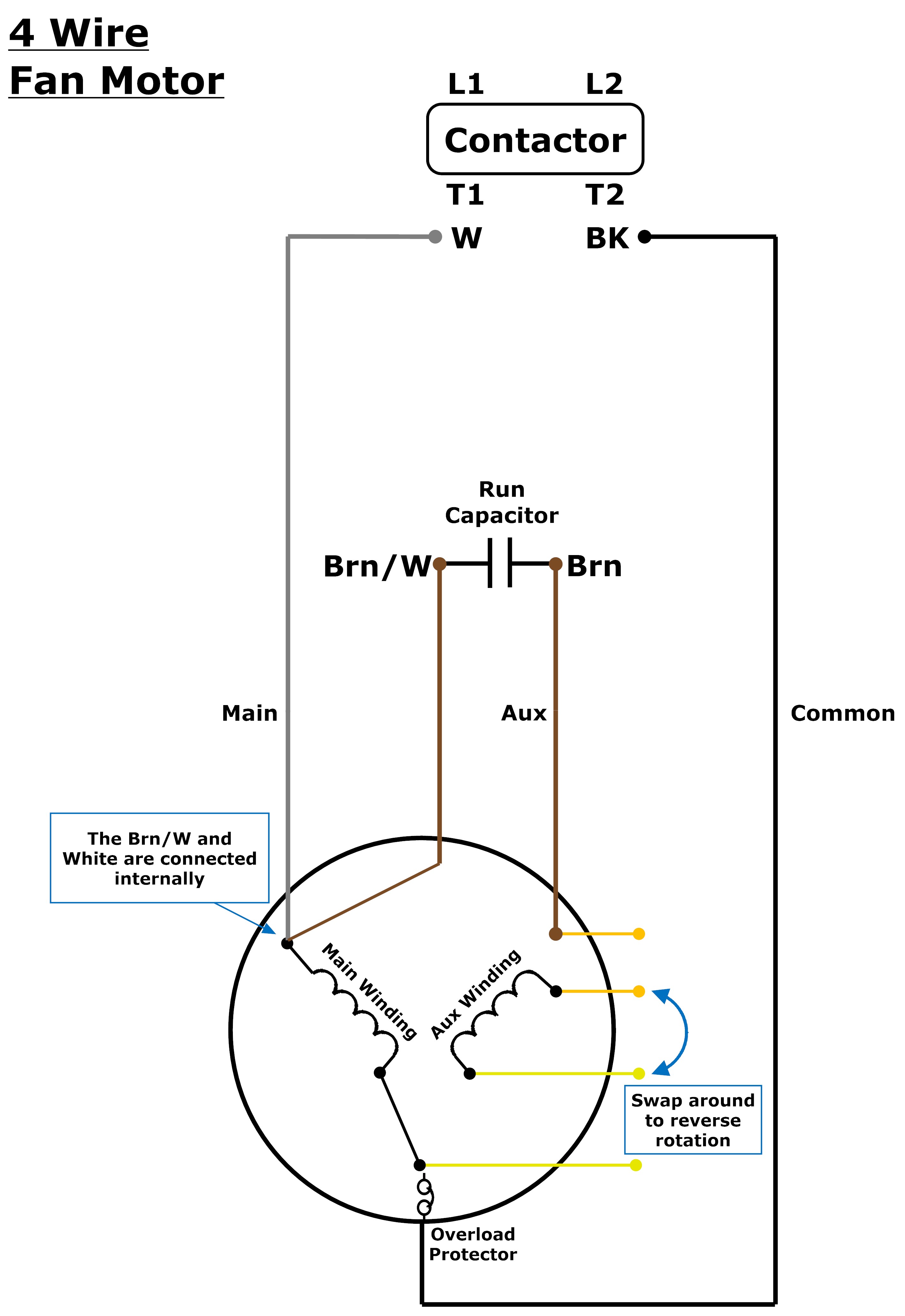
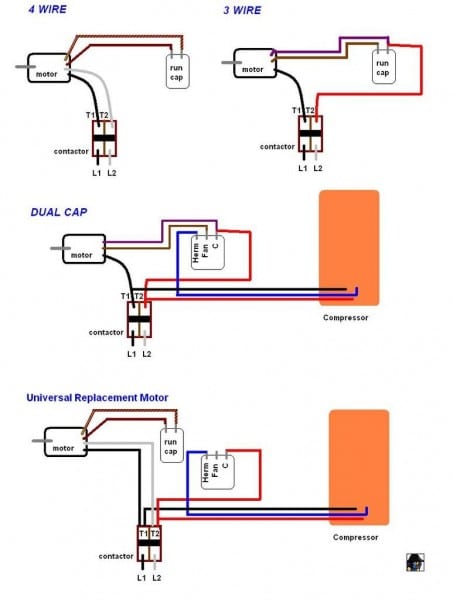
Wiring Diagram For Universal Condenser Fan Motor Wiring Diagram And In this episode we cover what the wiring diagram means on condenser motors and how to wire your new universal motor. update: if you want to see a longer brea. For a visual picture of typical wiring configurations, reference the following guide: hvac condenser fan motor wiring diagram. finally, this guide is intended to be used as a general overview of common condenser unit wiring schematics. some condenser fan motors wire to a circuit board while others use proprietary plugs for their connectors.

Condenser Fan Motor Wiring Diagram Reference When wiring a universal condenser fan motor, it is important to carefully follow the manufacturer’s instructions and consult the wiring diagram provided. this diagram will outline the specific wiring connections and color codes for the motor. it is crucial to correctly identify the motor’s voltage and speed settings to ensure proper operation. This diagram will illustrate the specific connections required for your motor model. the wiring diagram will typically show the power and neutral connections, as well as the wiring for the capacitor and speed selection wires. follow the color coding and connect each wire correctly. step 4: testing. Bryan explains the difference between 3 wire and 4 wire condenser fan motor wiring configurations. the differences between 3 wire and 4 wire configurations a. This is how to wire a 3 wire and 4 wire condenser fan motor into the outdoor unit. i go over how to eliminate the use of a second run capacitor when replacin.

Wiring A Universal Condenser Fan Motor Bryan explains the difference between 3 wire and 4 wire condenser fan motor wiring configurations. the differences between 3 wire and 4 wire configurations a. This is how to wire a 3 wire and 4 wire condenser fan motor into the outdoor unit. i go over how to eliminate the use of a second run capacitor when replacin. Cap off brown white (unused). now, for your 4 wire method: white wire from the condenser fan motor to one side of power on the contactor (t1). black wire from the condenser fan motor to the other side of power on the contactor (t2). brown wire from the condenser fan motor to the capacitor. again, this is ac power and not a dual capacitor, so. In this case, the two power wires—l1 and l2—are white and black and will mount to the t1 and t2 terminals of the contactor. these wires supply high voltage to the condenser fan motor once the contactor closes. the orange and yellow wires are the fan rotational wires. switching these wires will change the rotational spin of the fan.

Comments are closed.