Vrf System Cooling Flow Diagram

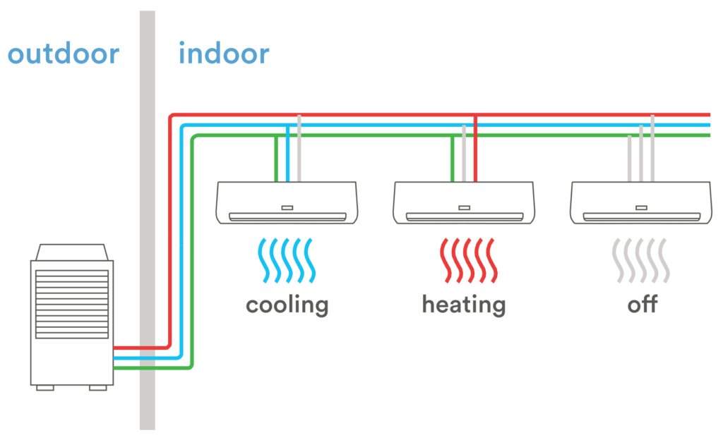
What Is Vrf In Hvac Ferguson Are also known as two pipe systems. cooling type vrf system . figure (source: fujitsu) vrf heat pump systems are effectively applied in open plan areas, retail stores, cellular offices and any other area that require cooling or heating during the same operational periods. hvac variable refrigerant flow (vrf) systems – m03 014 8. Vrf systems have been used in asia and europe for almost twenty five years. with a higher efficiency and increased controllability, the vrf system can help achieve a sustainable design. unfortu nately, the design of vrf systems is more complicated and requires additional work compared to designing a conventional dx system.
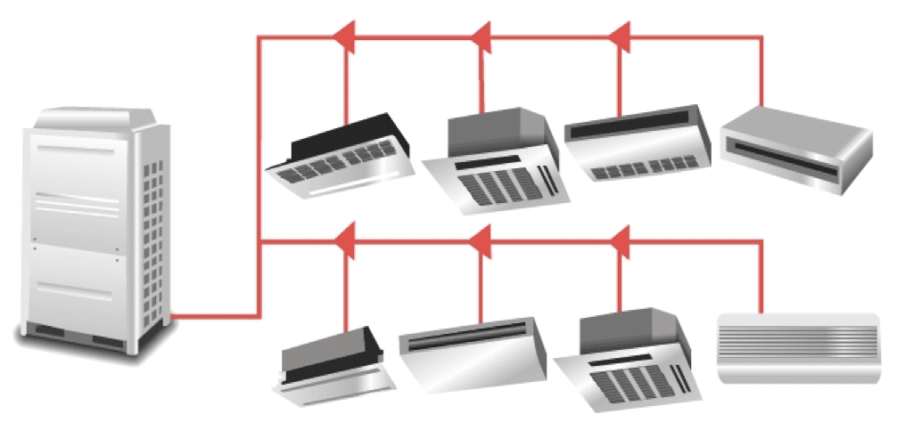
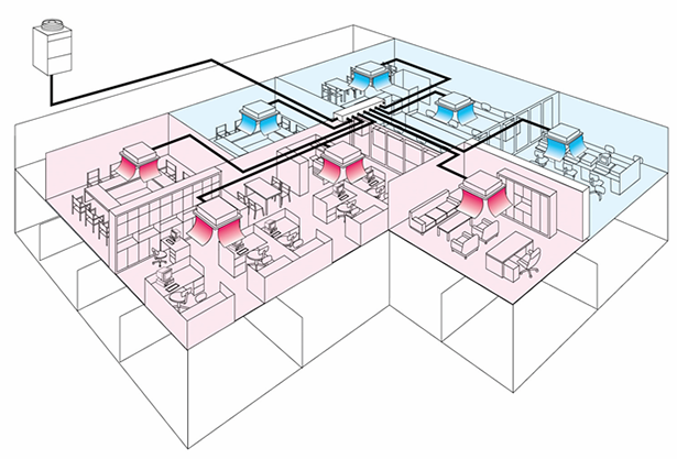
What Is A Vrf Air Conditioning System Wgi Variable refrigerant flow (vrf) systems have changed the game in commercial hvac. they offer unmatched efficiency and flexibility. these systems are now more popular, providing both heating and cooling to different areas in a building 18. they come in various sizes, from 18,000 to 760,000 btu h for outdoor units and 5,000 to 120,000 btu h for. The schematic diagram provides a visual representation of the system components, flow paths, and electrical connections. the vrf schematic diagram typically includes the following components: outdoor unit: this is the main component of the vrf system and contains the compressor, condenser, and other important parts. Addition, vrf systems do not experience the same energy losses as systems that move conditioned air through ductwork. however, differences in design the available in outdoor units will influence the efficiency level that is achieved. figure 4 – zoning layout for vrf system (cooling operation shown). Vrf stands for variable refrigerant flow, which goes a surprisingly long way toward describing how this system uses refrigerant for both air conditioning and heating. in a nutshell, vrf is a ductless, large scale system for hvac that performs at a high capacity. unlike split ac equipment, vrf allows multiple indoor units to run on the same.
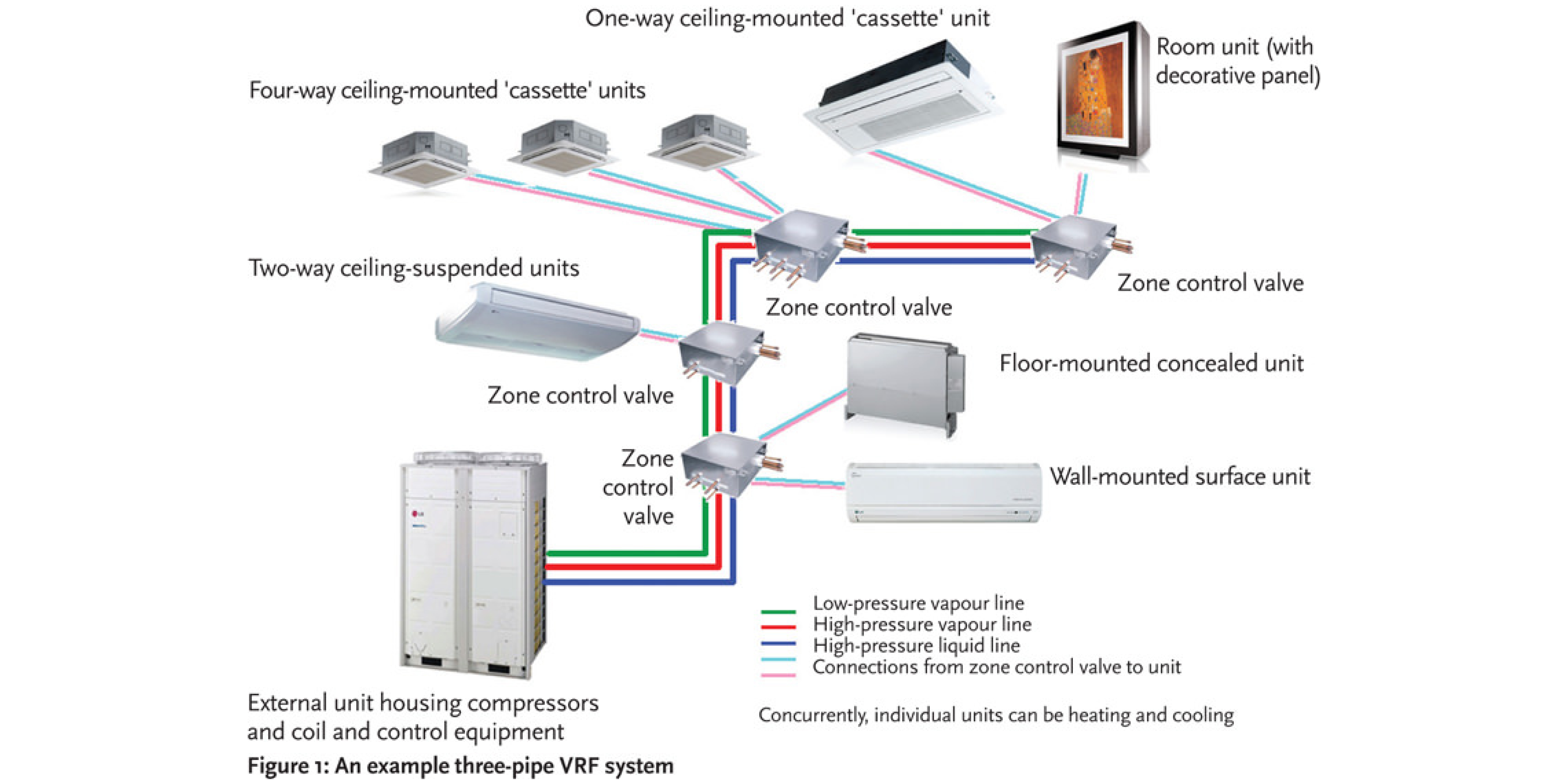
How Does A Water Cooled Vrf System Work Design Talk Addition, vrf systems do not experience the same energy losses as systems that move conditioned air through ductwork. however, differences in design the available in outdoor units will influence the efficiency level that is achieved. figure 4 – zoning layout for vrf system (cooling operation shown). Vrf stands for variable refrigerant flow, which goes a surprisingly long way toward describing how this system uses refrigerant for both air conditioning and heating. in a nutshell, vrf is a ductless, large scale system for hvac that performs at a high capacity. unlike split ac equipment, vrf allows multiple indoor units to run on the same. The term variable refrigerant flow (vrf) refers to the ability of the system to control the amount of refrigerant flowing to the multiple evaporators (indoor units), enabling the use of many evaporators of differing capacities and configurations connected to single condensing unit. the arrangement provides an individualized comfort control, and. Understanding the vrf schematic diagram is crucial for proper installation and maintenance of the system. it helps hvac technicians and engineers to diagnose any issues and make necessary repairs. the diagram also serves as a reference for troubleshooting and optimizing the system’s performance. in conclusion, the vrf schematic diagram is an.
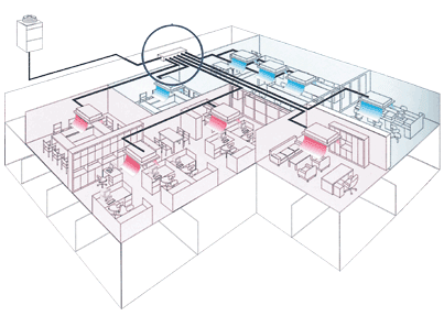
Variable Refrigerant Flow Systems Vrf Mission Mechanical The term variable refrigerant flow (vrf) refers to the ability of the system to control the amount of refrigerant flowing to the multiple evaporators (indoor units), enabling the use of many evaporators of differing capacities and configurations connected to single condensing unit. the arrangement provides an individualized comfort control, and. Understanding the vrf schematic diagram is crucial for proper installation and maintenance of the system. it helps hvac technicians and engineers to diagnose any issues and make necessary repairs. the diagram also serves as a reference for troubleshooting and optimizing the system’s performance. in conclusion, the vrf schematic diagram is an.
Tech Primer Variable Refrigerant Flow Vrf Systems Building Energy
Variable Refrigerant Flow Vrf Systems Efficiency Maine

Comments are closed.