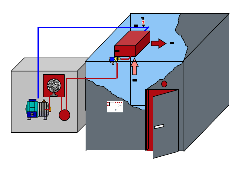
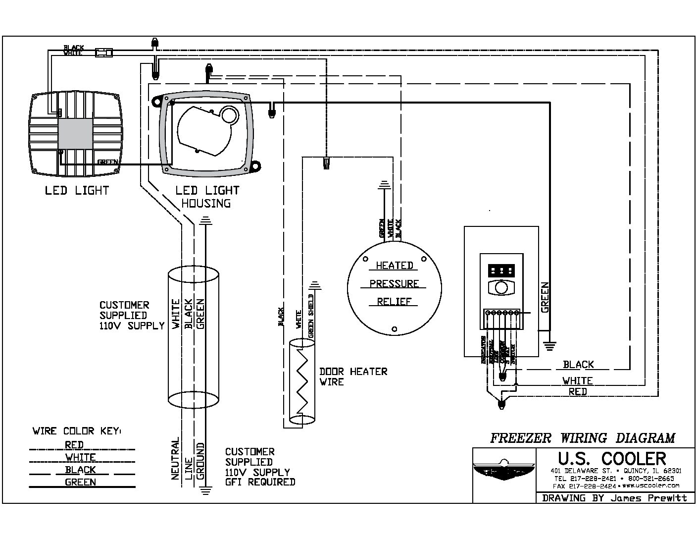
Walk In Cooler Refrigeration Diagram

Walk In Refrigeration A walk in cooler is a refrigerated storage unit that’s used to keep perishable goods at a safe temperature. the basic components of a walk in cooler include the walls, roof, floor, door, and refrigeration system. understanding how each of these parts works together is key to ensuring your walk in cooler is working optimally. Any refrigeration work should be done by a qualified and licensed refrigeration company. never work alone. always have another person helping or observing in case of an emergency. follow the installation and maintenance manual. the information is designed to assist in the proper method of assembling the walk in cooler and or freezer.

Walk In Cooler Parts Diagram Image To U Coolers, initial startup setting 4 @ 45 to 60 minutes.electric defrost on. zers, initial startup setting 4 @ 15 to 20 minutes. note: smart defrost (on demand defrost on lo. temperature coolers and freezers may be provided. proper installation an. Why u.s. cooler walk ins; walk in coolers; walk in freezers; walk in cooler freezer combo; brew cave® fastcooler; walk in add ons; replacement doors; replacement hardware; refrigeration; sales. why u.s. cooler walk ins; buying guide; contact a salesperson. east northeast territory; great lakes territory; mid atlantic territory; mid central. With the hooks pointing in the same direction as the pins on the cam locks in the floor, place the hooks of the threshold bar into the slots of the cams. push the bar in the direction of the pin of the cam lock until they contact. gently tap the locking bar until it locks into the cams or quits moving. this movement is about. 1 1⁄2”. Page 39 refer to the wiring diagram of the walk in cooler in the "electrical connections" section of this manual. hint: after positively identifying the two leads to the heater wire, cut the leads off, but leave an inch or two remaining on the switch terminal(s) and or wire connector.

Technical Walk In Drawings U S Cooler Walk Ins With the hooks pointing in the same direction as the pins on the cam locks in the floor, place the hooks of the threshold bar into the slots of the cams. push the bar in the direction of the pin of the cam lock until they contact. gently tap the locking bar until it locks into the cams or quits moving. this movement is about. 1 1⁄2”. Page 39 refer to the wiring diagram of the walk in cooler in the "electrical connections" section of this manual. hint: after positively identifying the two leads to the heater wire, cut the leads off, but leave an inch or two remaining on the switch terminal(s) and or wire connector. Area the walk in is to occupy. check the area for squareness by measuring diagonally across corners. find the highest point in the building floor and level from that point. if the walk in is larger than 10’ x 10’, use of a transit is recommended. 2. the levelness of the walk in floor is very important. the entire floor area must be. The refrigeration cycle. a walk in cooler refrigeration system operates through a sequence known as the refrigeration cycle. this cycle comprises four primary components: compressor. condenser. expansion valve. evaporator. the compressor. the compressor is the heart of the refrigeration cycle, pumping refrigerant gas throughout the system.

Basic Walk In Cooler Wiring Diagram Area the walk in is to occupy. check the area for squareness by measuring diagonally across corners. find the highest point in the building floor and level from that point. if the walk in is larger than 10’ x 10’, use of a transit is recommended. 2. the levelness of the walk in floor is very important. the entire floor area must be. The refrigeration cycle. a walk in cooler refrigeration system operates through a sequence known as the refrigeration cycle. this cycle comprises four primary components: compressor. condenser. expansion valve. evaporator. the compressor. the compressor is the heart of the refrigeration cycle, pumping refrigerant gas throughout the system.

Comments are closed.