Water Cooled Chiller Plant Diagram

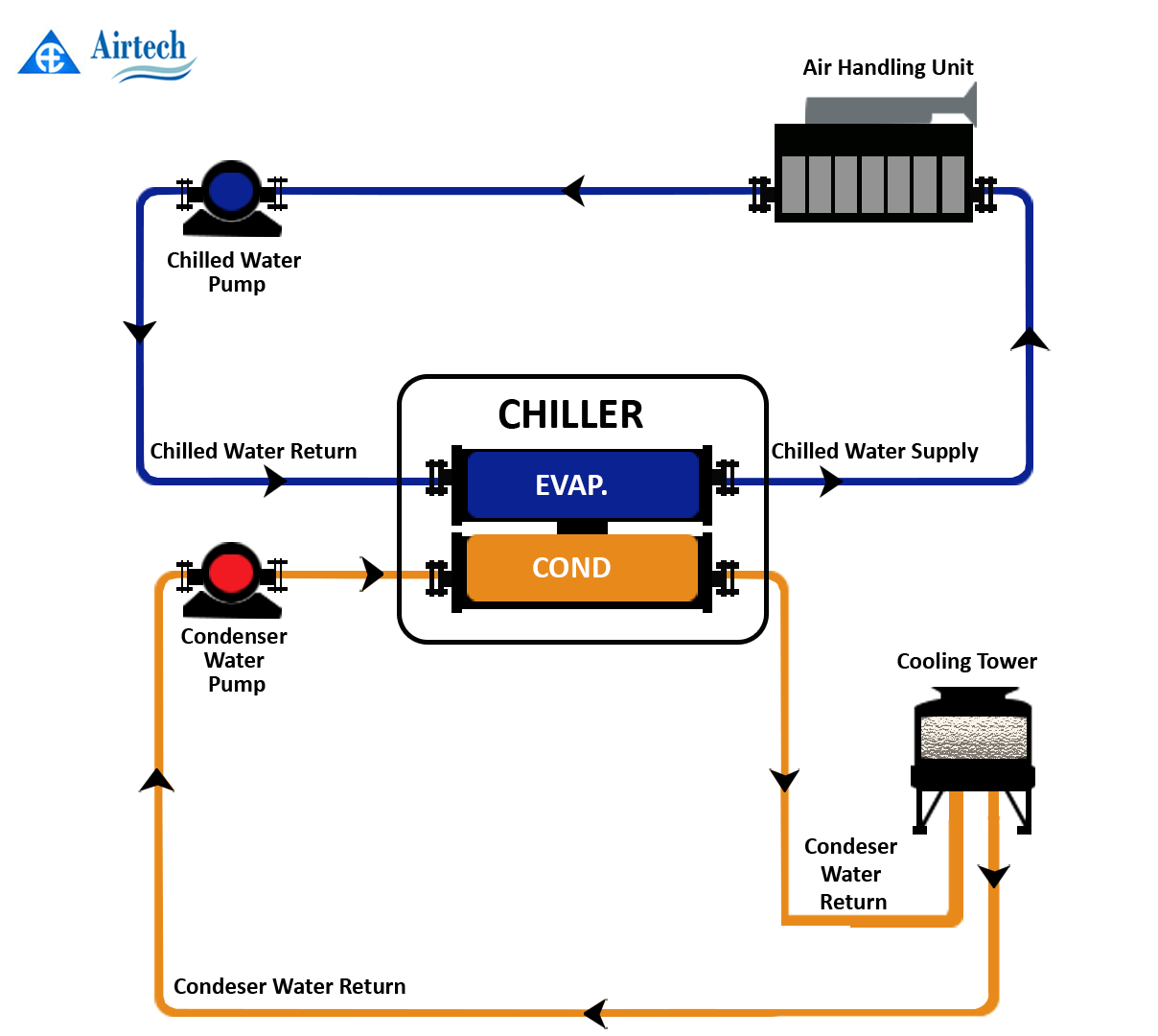
Water Cooled Chiller Diagram And The Measurement Points Download A chilled water system can be separated into water cooled and air cooled. water cooled chilled water systems are larger and more efficient than air cooled chilled water systems. a typical water cooled chilled water system consists of 4 major components as below: chiller. cooling tower. Sure setpoint or chilled water setpoint.select chiller for 2 to 4°f lower supply chilled water temperature than the cooling coils, to allow supply temperature reduction compensation for. irside low Δt or increased system load.install pressure independent cooling coil control valves to preserve system.

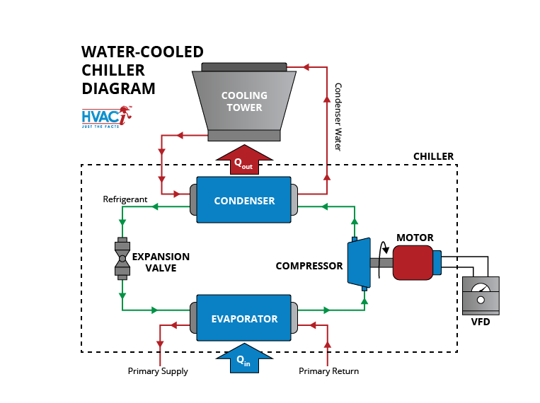
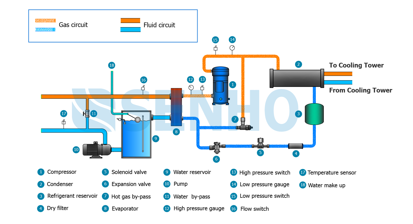
Diagram Water Cooled Chiller Plant Diagram Mydiagram Online The chilled water is generated and circulated in the primary side, the secondary loops will pull chilled water out of the header to cool the building and then dump the warm return back into the header. if the flow rate in the secondary side is low then some chilled water will flow into the secondary and some will recirculate back to the chillers. By mep academy instructor. november 10, 2023. 0. 7426. chilled water central plant basics. in this article we’ll discuss the basics of a chilled water central plant. the main pieces of equipment include a water cooled chiller, cooling tower, air handler, controls, and the chilled water and condenser water pumps. The main components of a water cooled chiller include the evaporator, compressor, condenser, expansion valve, water pump, and cooling tower. these components work together to remove heat from the process or system being cooled. the water cooled chiller schematic diagram depicts how the water circulates through these components, absorbing heat. The chilled water enters the evaporator at around 12 ° c (53.6 ° f). after the chilled water has transferred it’s heat over to the refrigerant, it will leave the evaporator at around 6°c (42.8°f). the refrigerant is picking up thermal energy but the temperature only changes slightly which confuses many people.

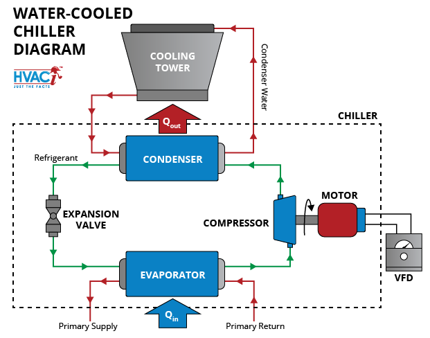
Water Cooled Chiller Diagram Hvac Investigators The main components of a water cooled chiller include the evaporator, compressor, condenser, expansion valve, water pump, and cooling tower. these components work together to remove heat from the process or system being cooled. the water cooled chiller schematic diagram depicts how the water circulates through these components, absorbing heat. The chilled water enters the evaporator at around 12 ° c (53.6 ° f). after the chilled water has transferred it’s heat over to the refrigerant, it will leave the evaporator at around 6°c (42.8°f). the refrigerant is picking up thermal energy but the temperature only changes slightly which confuses many people. This diagram is often used in the design and installation of water cooled chiller systems, as well as for troubleshooting and maintenance purposes. the diagram typically includes key components such as the chiller unit, cooling tower, pumps, water piping, and control valves. it also shows the flow of water and refrigerant through the system. Figure 37 shows a parallel water cooled chiller plant. chilled water is circulated by the chilled water or primary pump through both chillers to the load and back to the chillers. the chilled water loop can be either constant flow or variable flow. variable flow systems increase the complexity but offer significant pump work savings.

The Basics Of Chillers Hvac Investigators This diagram is often used in the design and installation of water cooled chiller systems, as well as for troubleshooting and maintenance purposes. the diagram typically includes key components such as the chiller unit, cooling tower, pumps, water piping, and control valves. it also shows the flow of water and refrigerant through the system. Figure 37 shows a parallel water cooled chiller plant. chilled water is circulated by the chilled water or primary pump through both chillers to the load and back to the chillers. the chilled water loop can be either constant flow or variable flow. variable flow systems increase the complexity but offer significant pump work savings.

Water Cooled Chiller System Diagram Pdf At Susan Orr Blog

Guide To Chilled Water Systems And Improving Efficiency Endocool

Comments are closed.